Cylinder Head Assembly
CYLINDER HEAD SET BOLT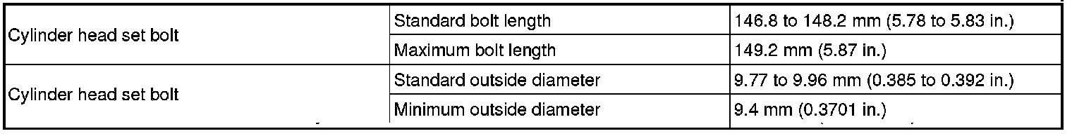
CYLINDER HEAD SUB-ASSEMBLY
The cylinder head bolts are tightened in 3 progressive steps.
Step 1

Using a 10 mm bi-hexagon wrench, install and uniformly tighten the 10 cylinder head bolts in several steps, in the sequence shown in the illustration.
Torque 49 Nm (500 kgf-cm, 36 ft-lbf)
Step 2

Text in Illustration
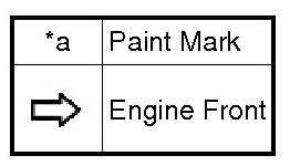
Mark each cylinder head bolt head with paint as shown in the illustration.
Tighten the cylinder head bolts 90° in the sequence shown in step 1.
Step 3
Tighten the cylinder head bolts another 45° in the sequence shown in step 1.
Check that the paint mark is now at a 135° angle to the front.
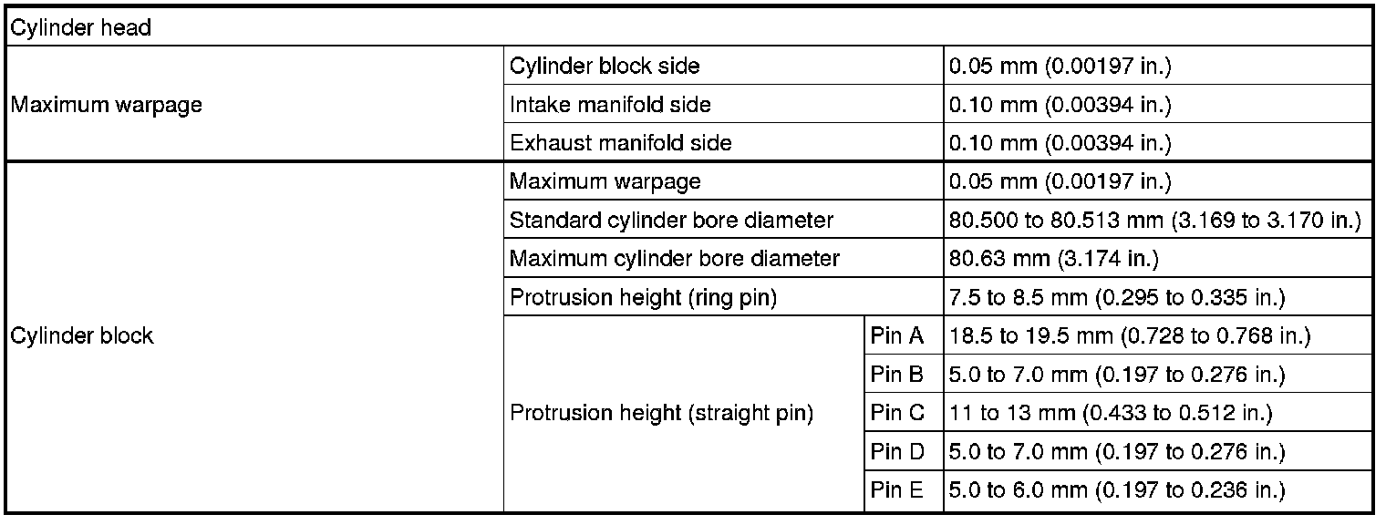
Surface Variation
CAMSHAFT BEARING CAP

Text in Illustration
Tighten the 10 bolts in the order shown in the illustration.

Torque 16 Nm (163 kgf-cm, 12 ft-lbf)
CAMSHAFT HOUSING SUB-ASSEMBLY

Install the camshaft housing sub-assembly with the 17 bolts and tighten them in the order shown in the illustration.
Torque 27 Nm (275 kgf-cm, 20 ft-lbf)
INTAKE MANIFOLD TORQUE & SEQUENCE Specifications
EXHAUST MANIFOLD TORQUE & SEQUENCE Specifications
CAMSHAFT GEAR/SPROCKET TORQUE Specifications