Part 1
U241E AUTOMATIC TRANSAXLE: AUTOMATIC TRANSAXLE UNIT: DISASSEMBLY
1. REMOVE SPEEDOMETER DRIVEN HOLE COVER SUB-ASSEMBLY
(a) Remove the bolt and hole cover from the transaxle.
(b) Remove the O-ring from the hole cover.
2. REMOVE PARK/NEUTRAL POSITION SWITCH ASSEMBLY
(a) Remove the nut, washer and control shaft lever.
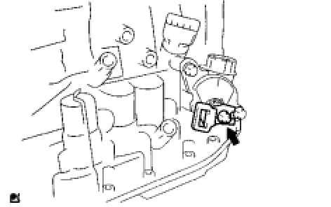
(b) Using a screwdriver, unstake the lock plate and remove the lock nut and lock plate.
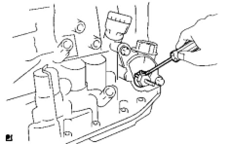
(c) Remove the 2 bolts and pull out the park/neutral position switch.
3. REMOVE BREATHER PLUG HOSE
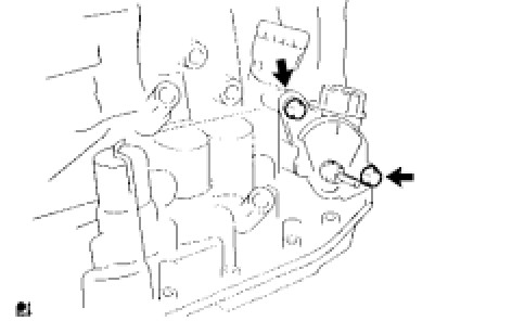
(a) Remove the breather plug hose from the breather plug.
4. REMOVE OIL COOLER OUTLET TUBE UNION
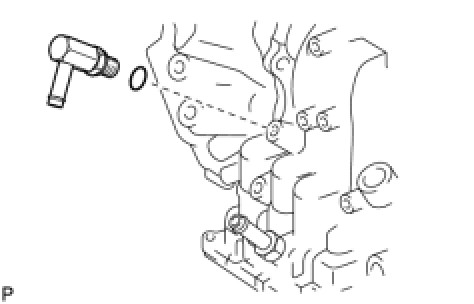
(a) Remove the union.
(b) Remove the O-ring from the union.
5. REMOVE OIL COOLER INLET TUBE UNION
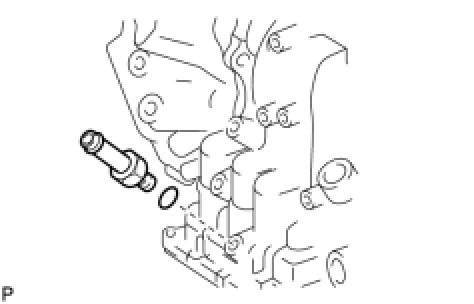
(a) Remove the union.
(b) Remove the O-ring from the union.
6. REMOVE SPEED SENSOR
(a) Remove the 2 bolts and 2 speed sensors from the transaxle.
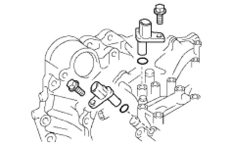
(b) Remove the 2 O-rings from the sensors.
7. REMOVE NO. 1 TRANSAXLE CASE PLUG
(a) Remove the 4 plugs from the transaxle.
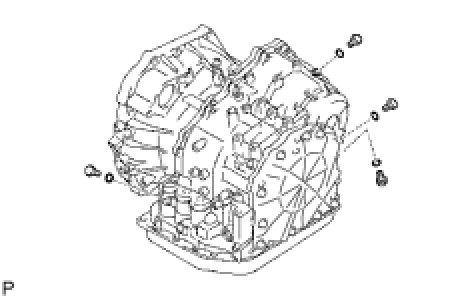
(b) Remove the 4 O-rings from the 4 plugs.
8. FIX AUTOMATIC TRANSAXLE ASSEMBLY
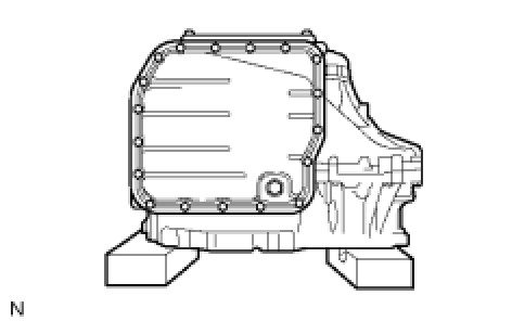
9. REMOVE AUTOMATIC TRANSAXLE OIL PAN SUB-ASSEMBLY
(a) Remove the 18 bolts.
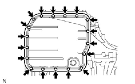
(b) Remove the oil pan and 3 magnets.
(c) Remove the gasket from the oil pan.
10. INSPECT AUTOMATIC TRANSAXLE OIL PAN SUB-ASSEMBLY Transaxle Unit
11. REMOVE VALVE BODY OIL STRAINER ASSEMBLY
(a) Remove the 3 bolts and oil strainer.
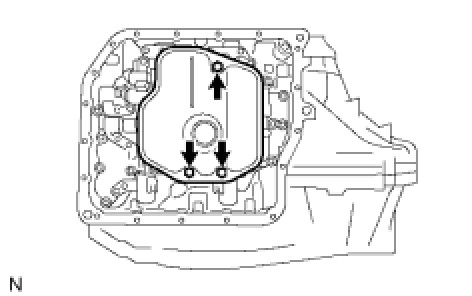
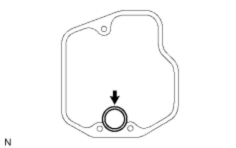
(b) Remove the O-ring from the oil strainer.
12. REMOVE TRANSMISSION WIRE
(a) Remove the 5 connectors from the shift solenoid valves.
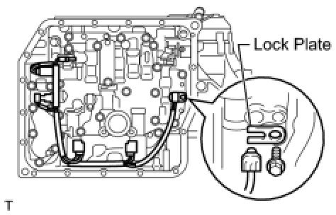
(b) Remove the bolt, clamp and ATF temperature sensor.
(c) Remove the bolt and transaxle solenoid wire from the transaxle.
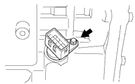
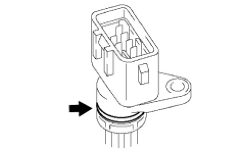
(d) Remove the O-ring from the transaxle solenoid wire.
13. REMOVE TRANSMISSION VALVE BODY ASSEMBLY
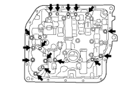
(a) Support the valve body assembly and remove the 17 bolts and the valve body assembly.
14. REMOVE NO. 1 GOVERNOR APPLY GASKET
(a) Remove the governor apply gasket from the transaxle.
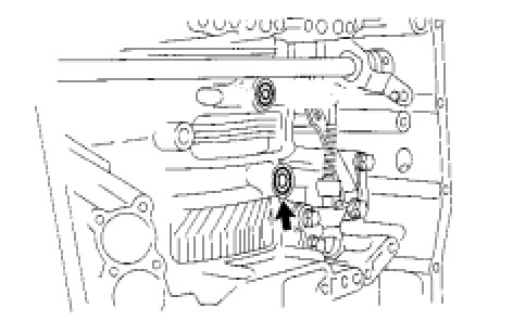
15. REMOVE TRANSAXLE CASE 2ND BRAKE GASKET
(a) Remove the 2nd brake gasket from the transaxle.
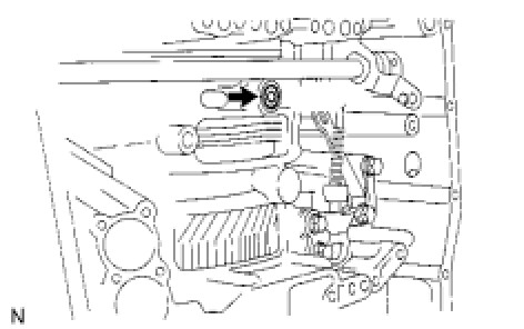
16. REMOVE BRAKE DRUM GASKET
(a) Remove the brake drum gasket from the transaxle.
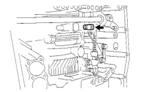
17. REMOVE CHECK BALL BODY
(a) Remove the check ball body and spring from the transaxle.
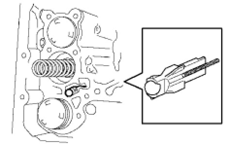
18. REMOVE C-3 ACCUMULATOR PISTON
(a) Remove the compression spring from the C-3 accumulator piston.
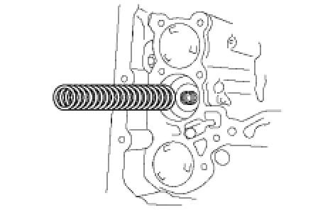
(b) Apply compressed air (392 kPa, 4.0 kgf/cm2, 57 psi) to the oil hole and remove the C-3 accumulator piston.
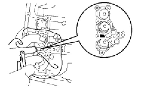
NOTICE:
* Applying compressed air may cause the piston to jump out. When removing the piston, hold it with your hand using a waste cloth.
* Make sure not to spatter ATF when applying compressed air.
(c) Remove the O-ring from the C-3 accumulator piston.
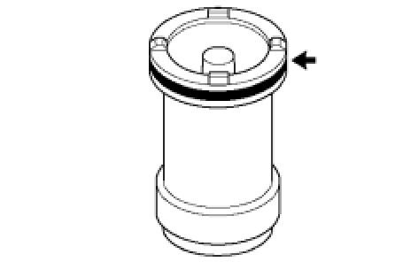
19. REMOVE C-1 ACCUMULATOR PISTON
(a) Apply compressed air (392 kPa, 4.0 kgf/cm2, 57 psi) to the oil hole and remove the C-1 accumulator piston and compression spring.
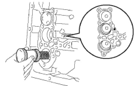
NOTICE:
* Applying compressed air may cause the piston to jump out. When removing the piston, hold it with your hand using a waste cloth.
* Make sure not to spatter ATF when applying compressed air.
(b) Remove the 2 O-rings from the C-1 accumulator piston.
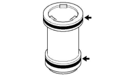
20. REMOVE B-3 ACCUMULATOR PISTON
(a) Apply compressed air (392 kPa, 4.0 kgf/cm2, 57 psi) to the oil hole and remove the B-3 accumulator piston and 2 compression springs.
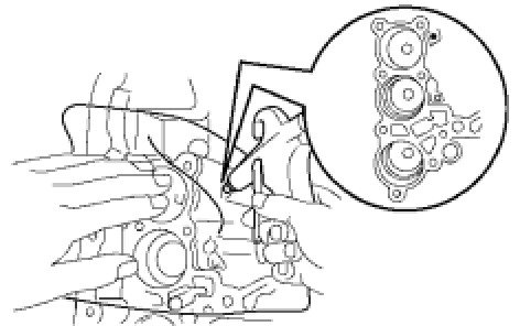
NOTICE:
* Applying compressed air may cause the piston to jump out. When removing the piston, hold it with your hand using a waste cloth.
* Make sure not to spatter ATF when applying compressed air.
(b) Remove the O-ring from the B-3 accumulator piston.
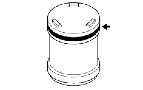
21. REMOVE MANUAL DETENT SPRING SUB-ASSEMBLY
(a) Remove the 2 bolts, manual detent spring and cover.
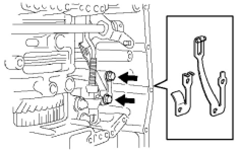
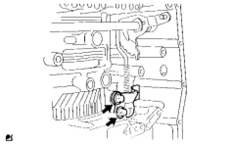
22. REMOVE PARKING LOCK PAWL BRACKET
(a) Remove the 2 bolts and parking lock pawl bracket.
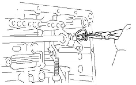
23. REMOVE MANUAL VALVE LEVER SHAFT RETAINER SPRING
(a) Using needle-nose pliers, remove the retainer spring.
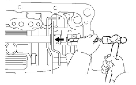
24. REMOVE MANUAL VALVE LEVER SUB-ASSEMBLY
(a) Using a chisel and hammer, unstake and remove the manual valve lever spacer.
(b) Using a pin punch and hammer, tap out the manual valve lever shaft spring pin.
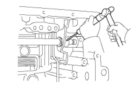
HINT
Slowly drive out the pin so that it will not fall into the transaxle.
(c) Remove the manual valve lever shaft and manual valve lever.
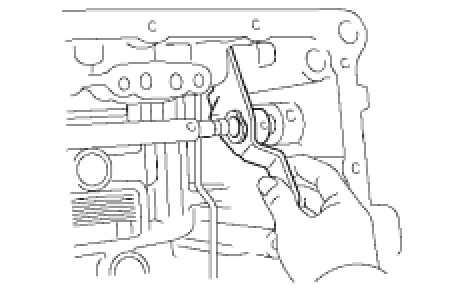
25. REMOVE PARKING LOCK ROD SUB-ASSEMBLY
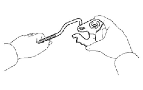
(a) Remove the parking lock rod from the manual valve lever.