Part 1
NETWORKING: CAN COMMUNICATION SYSTEM: TERMINALS OF ECU
HINT
Operating the ignition switch, any switches or any doors triggers related ECU and sensor communication with the CAN, which causes resistance variation.
1. DISCONNECT CABLE FROM NEGATIVE BATTERY TERMINAL
(a) Disconnect the cable from the negative (-) battery terminal before measuring the resistances of the CAN main wire and the CAN branch wire.
CAUTION:
Wait at least 90 seconds after disconnecting the cable from the negative (-) battery terminal to disable the SRS system.
NOTICE:
* Before measuring the resistance, leave the vehicle for at least 1 minute and do not operate the ignition switch, any switches or any doors. If doors need to be opened in order to check connectors, open the doors and leave them open.
* When disconnecting the cable, some systems need to be initialized after the cable is reconnected Repair Instruction - Initialization.
* After turning the ignition switch off, waiting time may be required before disconnecting the cable from the battery terminal. Therefore, make sure to read the disconnecting the cable from the battery terminal notice before proceeding with work Service Precautions.
2. JUNCTION CONNECTOR
(a) NO. 1 JUNCTION CONNECTOR
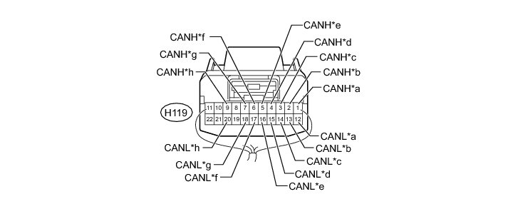
Text in Illustration
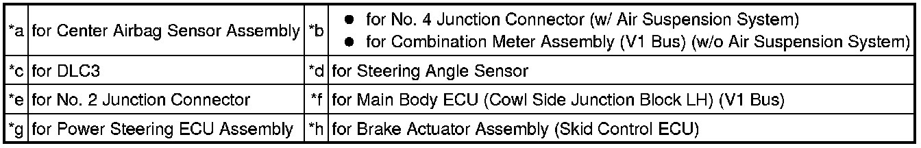
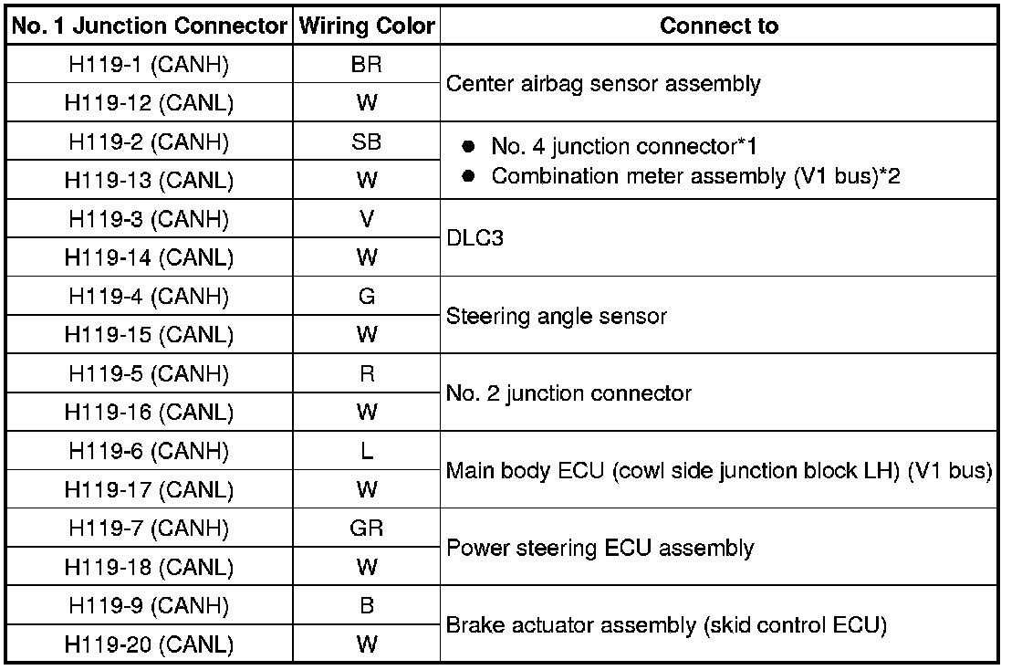
* *1: w/ Air Suspension System
* *2: w/o Air Suspension System
(b) NO. 2 JUNCTION CONNECTOR
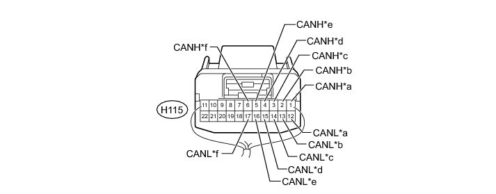
Text in Illustration
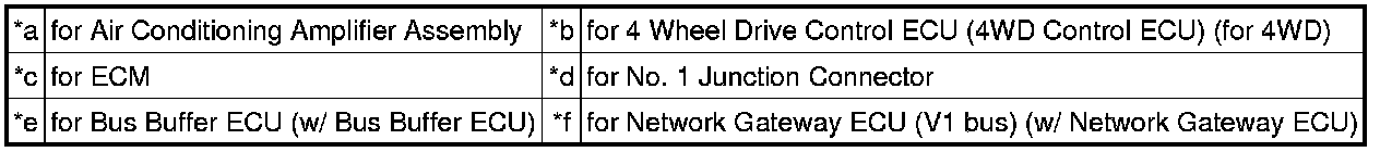
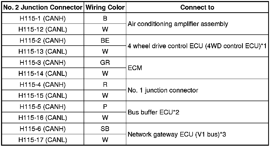
* *1: for 4WD
* *2: w/ Bus Buffer ECU
* *3: w/ Network Gateway ECU
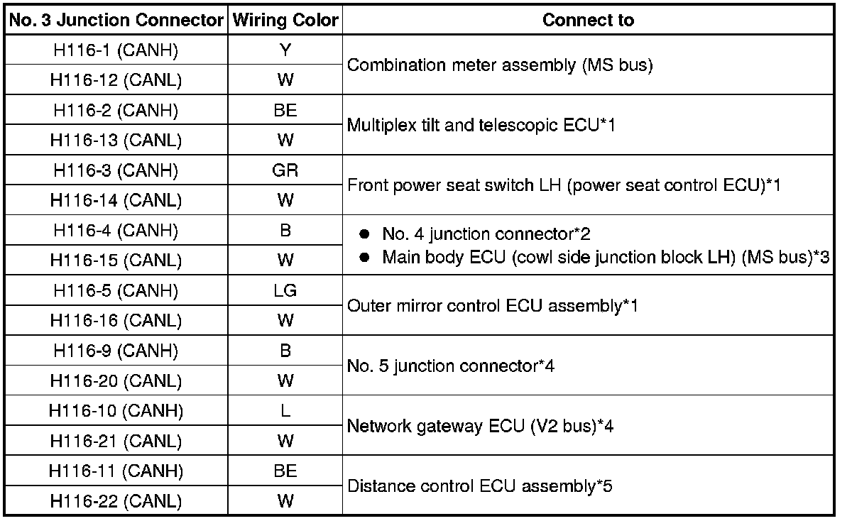
(c) NO. 3 JUNCTION CONNECTOR
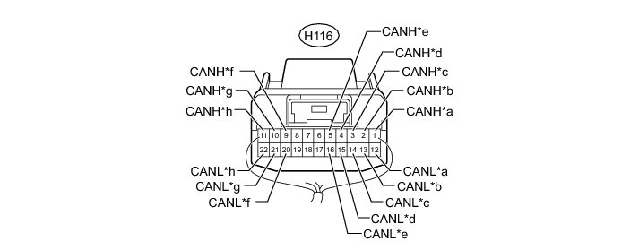
Text in Illustration
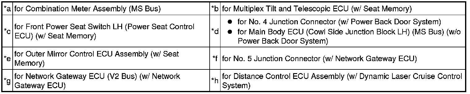
* *1: w/ Seat Memory
* *2: w/ Power Back Door System
* *3: w/o Power Back Door System
* *4: w/ Network Gateway ECU
* *5: w/ Dynamic Laser Cruise Control System
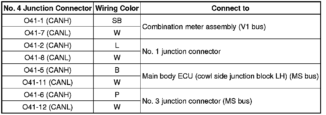
(d) NO. 4 JUNCTION CONNECTOR (FRONT OF THE VEHICLE) (w/ Power Back Door System or w/ Air Suspension System)
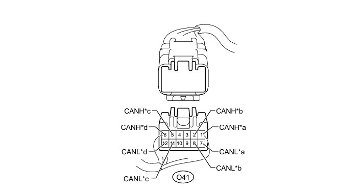
Text in Illustration

(e) NO. 4 JUNCTION CONNECTOR (REAR OF THE VEHICLE) (w/ Power Back Door System or w/ Air Suspension System)
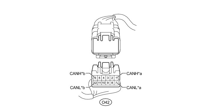
Text in Illustration

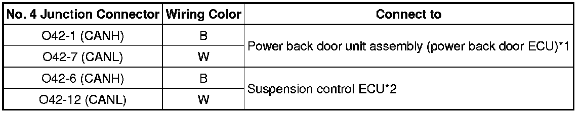
* *1: w/ Power Back Door System
* *2: w/ Air Suspension System
(f) NO. 5 JUNCTION CONNECTOR (w/ Network Gateway ECU)
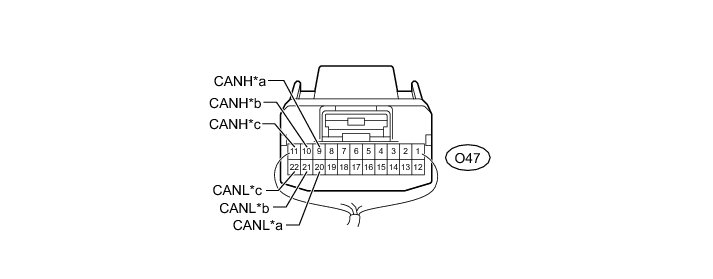
Text in Illustration

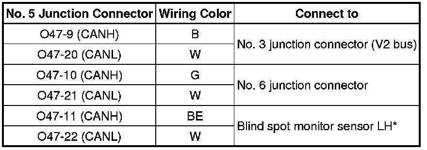
* *: w/ Blind Spot Monitor Sensor
(g) NO. 6 JUNCTION CONNECTOR (w/ Network Gateway ECU)

Text in Illustration

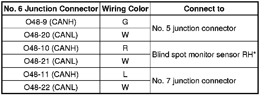
* *: w/ Blind Spot Monitor Sensor
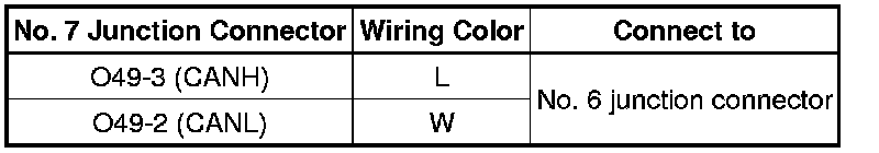
(h) NO. 7 JUNCTION CONNECTOR (w/ Network Gateway ECU)
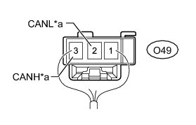
Text in Illustration
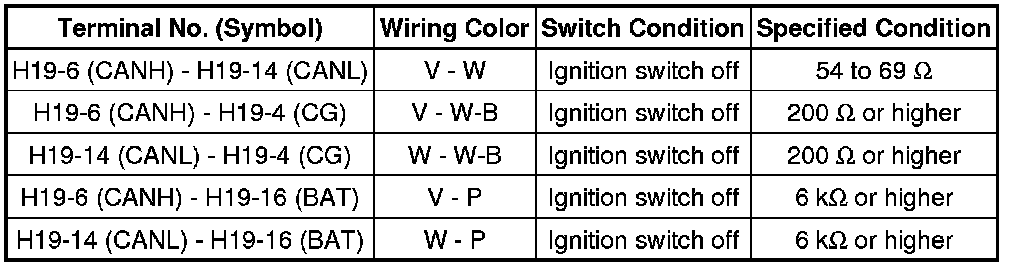
3. CHECK DLC3
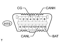
(a) Disconnect the cable from the negative (-) battery terminal before measuring the resistances of the CAN main wire and the CAN branch wire.
CAUTION:
Wait at least 90 seconds after disconnecting the cable from the negative (-) battery terminal to disable the SRS system.
NOTICE:
When disconnecting the cable, some systems need to be initialized after the cable is reconnected Repair Instruction - Initialization.
(b) Measure the resistance according to the value(s) in the table below.
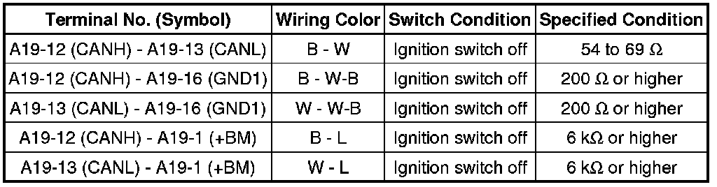
4. CHECK BRAKE ACTUATOR ASSEMBLY (SKID CONTROL ECU)
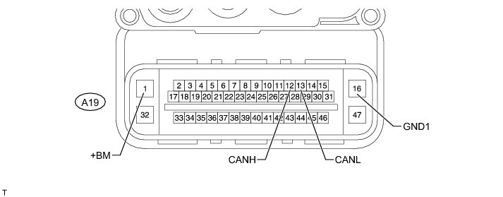
(a) Disconnect the A19 brake actuator assembly (skid control ECU) connector.
(b) Measure the resistance according to the value(s) in the table below.
5. CHECK MAIN BODY ECU (COWL SIDE JUNCTION BLOCK LH)
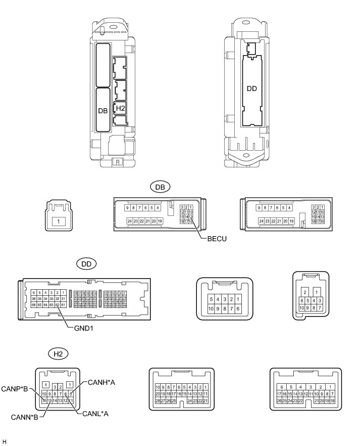
Text in Illustration

(a) Disconnect the H2, DB and DD main body ECU (cowl side junction block LH) connectors.
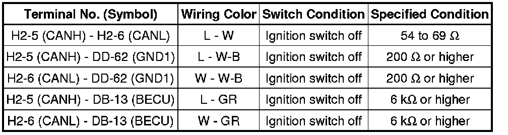
(b) Measure the resistance according to the value(s) in the table below.
for V1 Bus
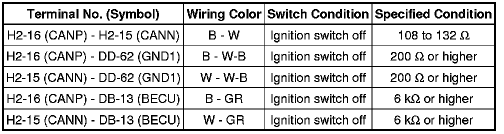
for MS Bus
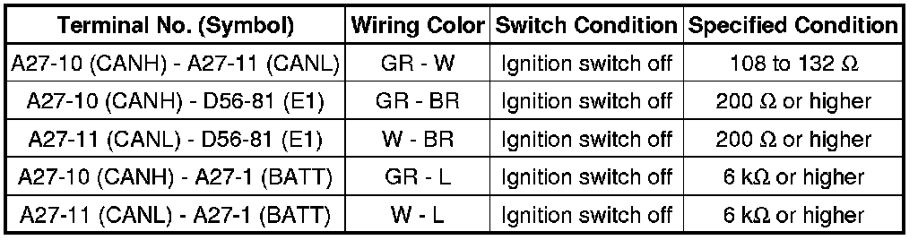
6. CHECK ECM
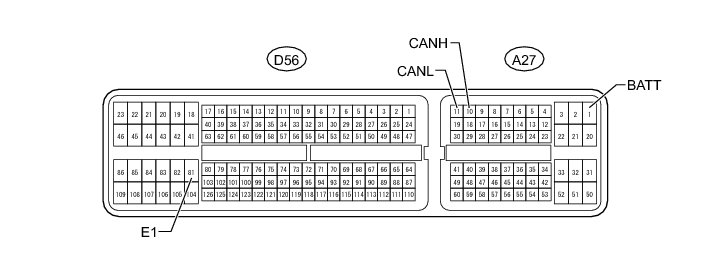
(a) Disconnect the A27 and D56 ECM connectors.
(b) Measure the resistance according to the value(s) in the table below.
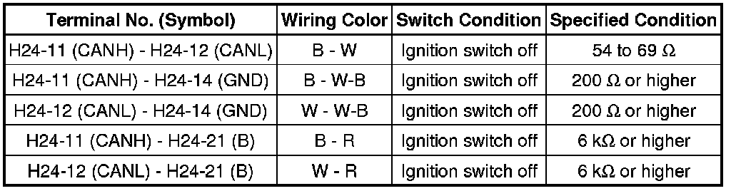
7. CHECK AIR CONDITIONING AMPLIFIER ASSEMBLY
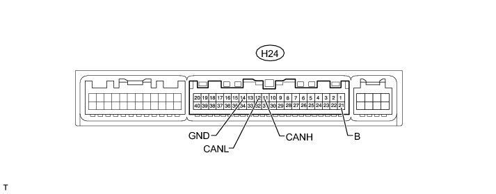
(a) Disconnect the H24 air conditioning amplifier assembly connector.
(b) Measure the resistance according to the value(s) in the table below.
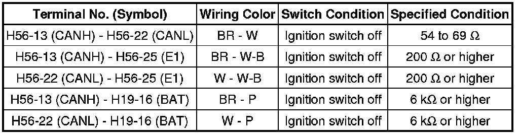
8. CHECK CENTER AIRBAG SENSOR ASSEMBLY
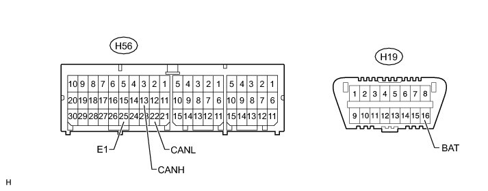
(a) Disconnect the H56 center airbag sensor assembly connector.
(b) Measure the resistance according to the value(s) in the table below.
9. CHECK COMBINATION METER ASSEMBLY
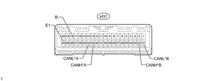
Text in Illustration

(a) Disconnect the H37 combination meter assembly connector.
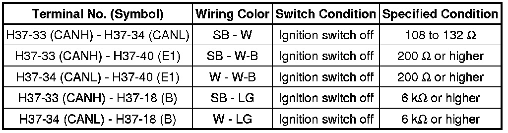
(b) Measure the resistance according to the value(s) in the table below.
for V1 Bus
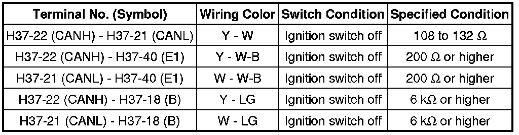
for MS Bus
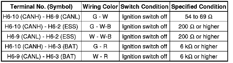
10. CHECK STEERING ANGLE SENSOR
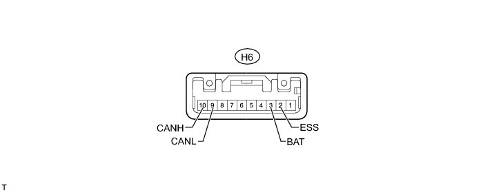
(a) Disconnect the H6 steering angle sensor connector.
(b) Measure the resistance according to the value(s) in the table below.
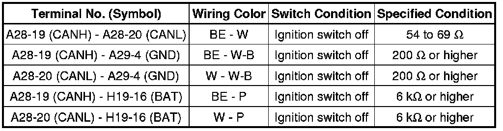
11. CHECK 4 WHEEL DRIVE CONTROL ECU (4WD CONTROL ECU) (for 4WD)
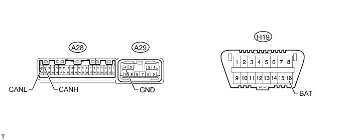
(a) Disconnect the A28 and A29 4 wheel drive control ECU (4WD control ECU) connectors.
(b) Measure the resistance according to the value(s) in the table below.