Part 2
NETWORKING: CAN COMMUNICATION SYSTEM: TERMINALS OF ECU - (Continued)
12. CHECK BUS BUFFER ECU (w/ Bus Buffer ECU)
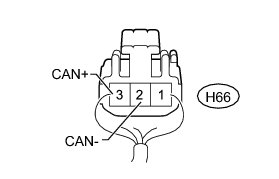
(a) Disconnect the H66 bus buffer ECU connector.
(b) Measure the resistance according to the value(s) in the table below.

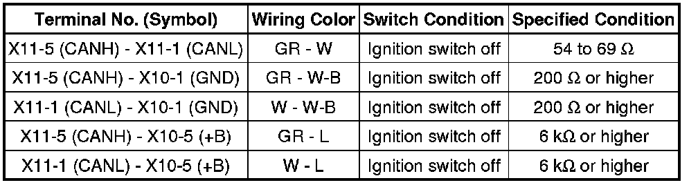
13. CHECK FRONT POWER SEAT SWITCH LH (POWER SEAT CONTROL ECU) (w/ Seat Memory)
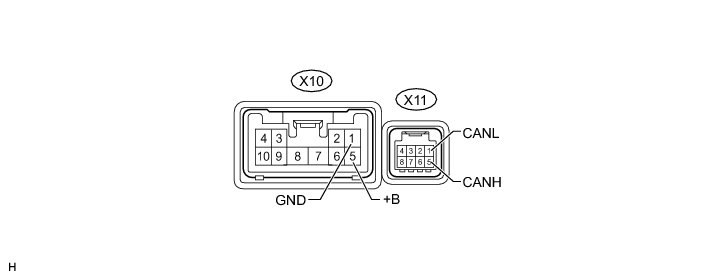
(a) Disconnect the X10 and X11 front power seat switch LH (power seat control ECU) connectors.
(b) Measure the resistance according to the value(s) in the table below.
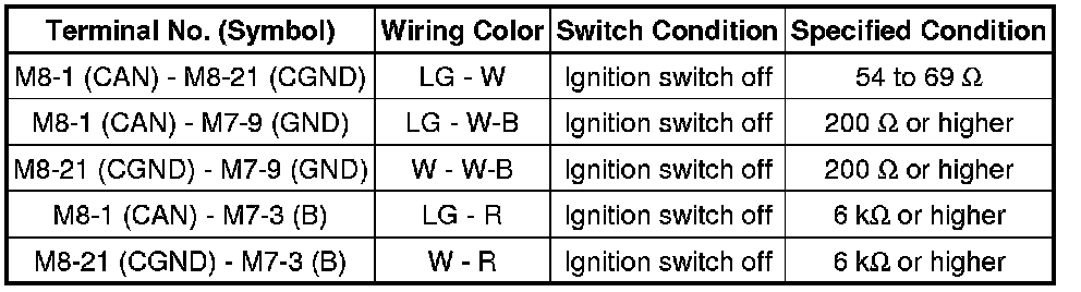
14. CHECK OUTER MIRROR CONTROL ECU ASSEMBLY (w/ Seat Memory)
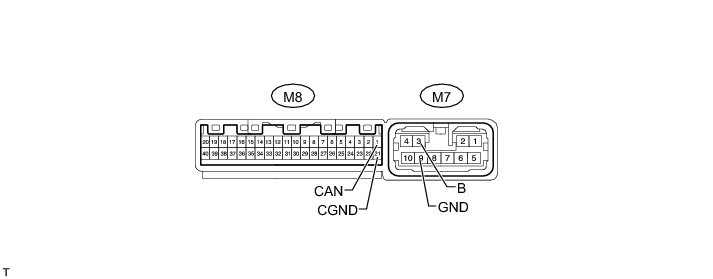
(a) Disconnect the M7 and M8 outer mirror control ECU assembly connectors.
(b) Measure the resistance according to the value(s) in the table below.
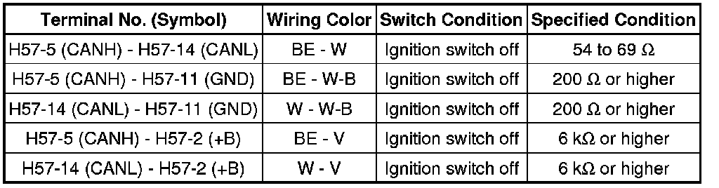
15. CHECK MULTIPLEX TILT AND TELESCOPIC ECU (w/ Seat Memory)
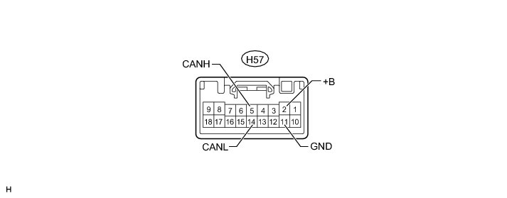
(a) Disconnect the H57 multiplex tilt and telescopic ECU connector.
(b) Measure the resistance according to the value(s) in the table below.
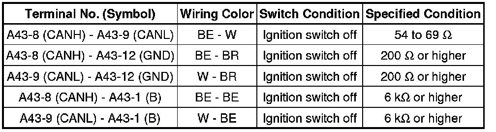
16. CHECK DISTANCE CONTROL ECU ASSEMBLY (w/ Dynamic Laser Cruise Control System)
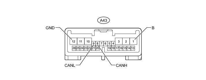
(a) Disconnect the A43 distance control ECU assembly connector.
(b) Measure the resistance according to the value(s) in the table below.
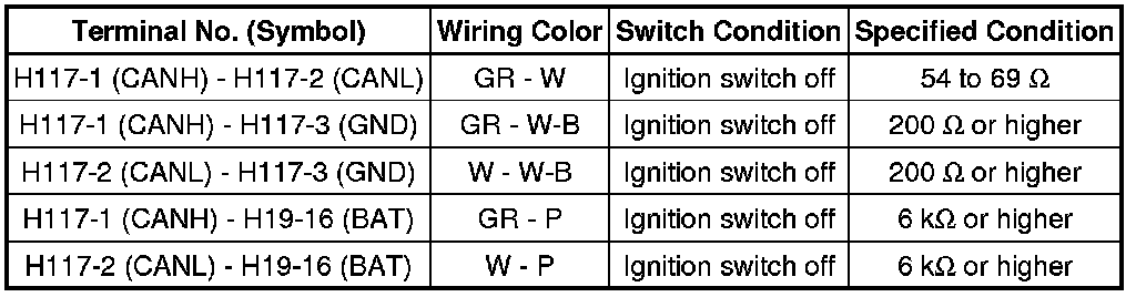
17. CHECK POWER STEERING ECU ASSEMBLY
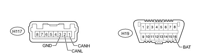
(a) Disconnect the H117 power steering ECU assembly connector.
(b) Measure the resistance according to the value(s) in the table below.
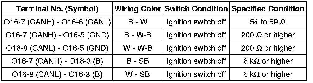
18. CHECK SUSPENSION CONTROL ECU (w/ Air Suspension System)
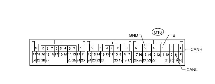
(a) Disconnect the O16 suspension control ECU connector.
(b) Measure the resistance according to the value(s) in the table below.
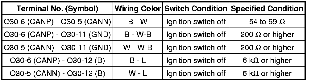
19. CHECK POWER BACK DOOR UNIT ASSEMBLY (POWER BACK DOOR ECU) (w/ Power Back Door System)
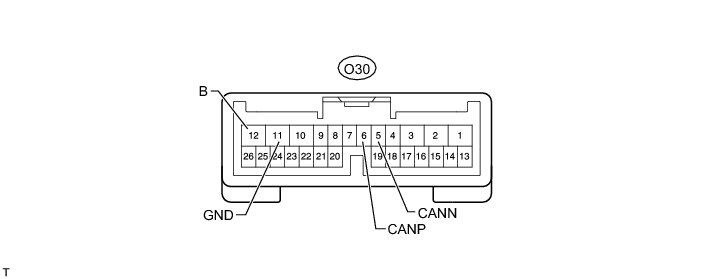
(a) Disconnect the O30 power back door unit assembly (power back door ECU) connector.
(b) Measure the resistance according to the value(s) in the table below.
20. CHECK NETWORK GATEWAY ECU (w/ Network Gateway ECU)
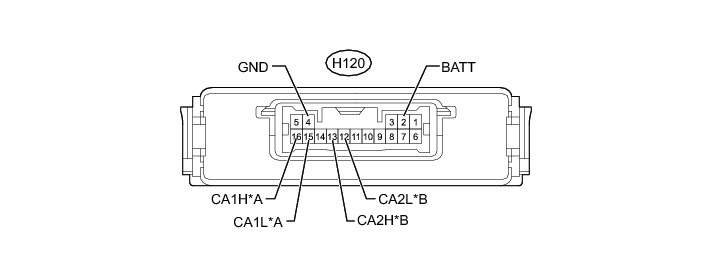
Text in Illustration

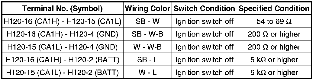
(a) Disconnect the H120 network gateway ECU connector.
(b) Measure the resistance according to the value(s) in the table below.
for V1 Bus
for V2 Bus

21. CHECK BLIND SPOT MONITOR SENSOR LH (w/ Blind Spot Monitor Sensor)
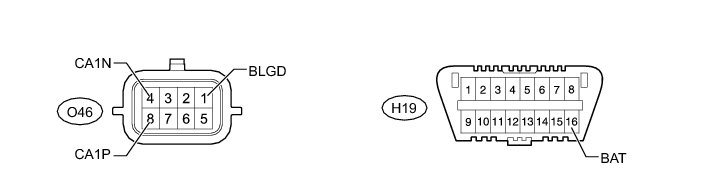
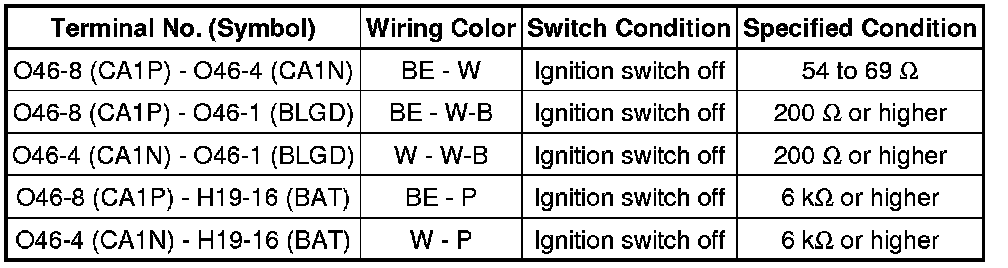
(a) Disconnect the O46 blind spot monitor sensor LH connector.
(b) Measure the resistance according to the value(s) in the table below.
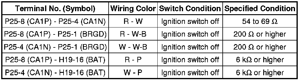
22. CHECK BLIND SPOT MONITOR SENSOR RH (w/ Blind Spot Monitor Sensor)

(a) Disconnect the P25 blind spot monitor sensor RH connector.
(b) Measure the resistance according to the value(s) in the table below.