Part 2
2TR-FE ENGINE MECHANICAL: ENGINE UNIT: INSPECTION (Continued)
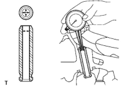
28. INSPECT INNER COMPRESSION SPRING
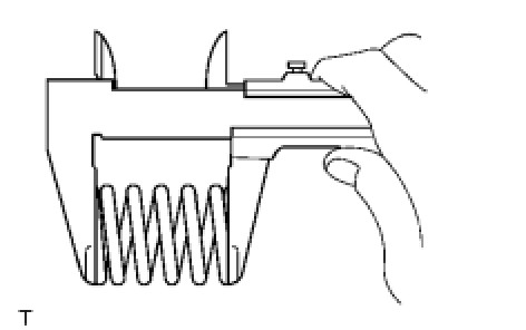
(a) Using vernier calipers, measure the free length of the inner compression spring.
Free length:
48.53 mm (1.9106 in.)
If the free length is not as specified, replace the spring.
(b) Using a steel square, measure the deviation of the inner compression spring.
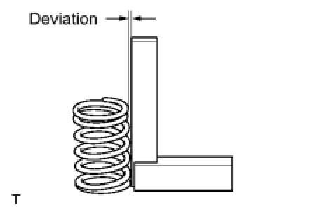
Maximum deviation:
1.5 mm (0.059 in.)
Maximum angle (reference):
2°
If the deviation is greater than the maximum, replace the spring.
29. INSPECT INTAKE VALVE
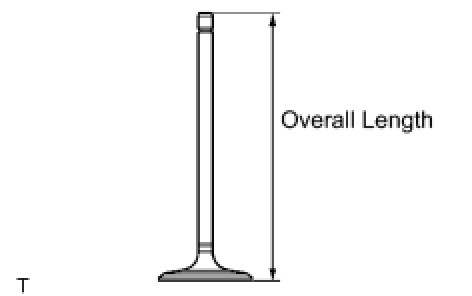
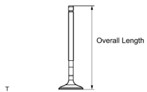
(a) Using vernier calipers, measure the valve's overall length.
Standard overall length:
106.26 mm (4.1835 in.)
Minimum overall length:
105.96 mm (4.1716 in.)
If the overall length is less than the minimum, replace the valve.
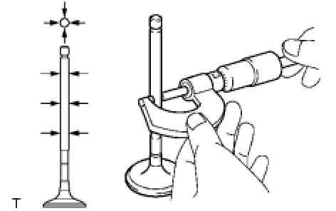
(b) Using a micrometer, measure the diameter of the valve stem.
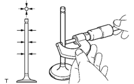
Valve stem diameter:
5.470 to 5.485 mm (0.2154 to 0.2159 in.)
(c) Using vernier calipers, measure the valve head margin thickness.
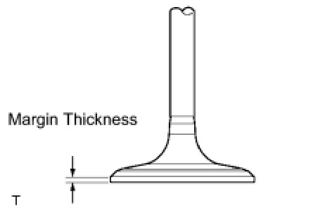
Standard margin thickness:
1.05 to 1.45 mm (0.0413 to 0.0571 in.)
Minimum margin thickness:
0.50 mm (0.0197 in.)
Thickness If the margin thickness is less than the minimum, replace the valve.
30. INSPECT EXHAUST VALVE
(a) Using vernier calipers, measure the valve's overall length.
Standard overall length:
106.74 mm (4.2024 in.)
Minimum overall length:
106.44 mm (4.1905 in.)
If the overall length is less than the minimum, replace the valve.
(b) Using a micrometer, measure the diameter of the valve stem.
Valve stem diameter:
5.465 to 5.480 mm (0.2151 to 0.2157 in.)
(c) Using vernier calipers, measure the valve head margin thickness.
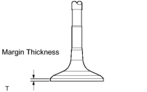
Standard margin thickness:
1.2 to 1.6 mm (0.0472 to 0.0630 in.)
Minimum margin thickness:
0.50 mm (0.0197 in.)
If the margin thickness is less than the minimum, replace the valve.
31. INSPECT VALVE GUIDE BUSHING
(a) Using a caliper gauge, measure the inside diameter of the guide bush.
Bush inside diameter:
5.510 to 5.530 mm (0.2169 to 0.2177 in.)
(b) Subtract the valve stem diameter measurement from the guide bush inside diameter measurement.
Standard oil clearance:
0.025 to 0.060 mm (0.0010 to 0.0024 in.) (Intake)
0.030 to 0.065 mm (0.0012 to 0.0026 in.) (Exhaust)
Maximum oil clearance:
0.08 mm (0.0032 in.) (Intake)
0.10 mm (0.0039 in.) (Exhaust)
HINT
* If the clearance is greater than the maximum, replace the intake valve and intake guide bush.
* If the clearance is greater than the maximum, replace the exhaust valve and exhaust guide bush.
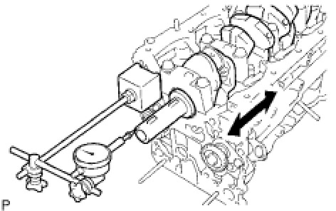
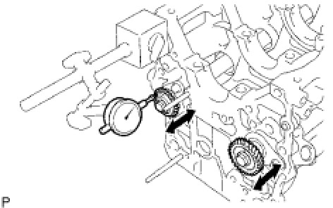
32. INSPECT CONNECTING ROD THRUST CLEARANCE
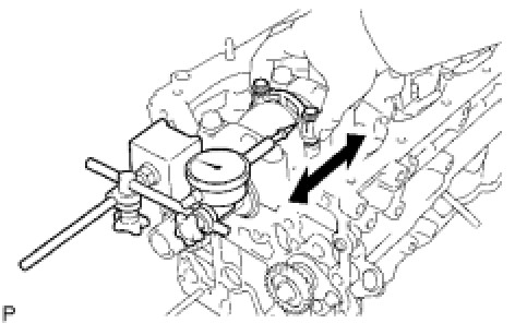
(a) Using a dial indicator, measure the thrust clearance while moving the connecting rod back and forth.
Standard thrust clearance:
0.150 to 0.350 mm (0.0059 to 0.0138 in.)
Maximum thrust clearance:
0.40 mm (0.016 in.)
If the thrust clearance is greater than the maximum, replace the connecting rod assembly(s). If necessary, replace the crankshaft.
33. INSPECT CONNECTING ROD OIL CLEARANCE
(a) Check that the matchmarks on the connecting rod and cap are aligned to ensure the correct reassembly.
HINT
The matchmarks on the connecting rods and caps are for ensuring the correct reassembly.
(b) Remove the 2 connecting rod cap bolts.
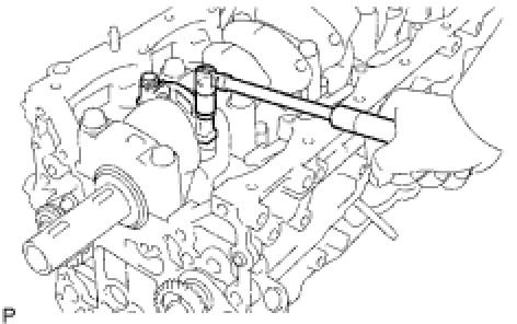
(c) Using the 2 removed connecting rod cap bolts, remove the connecting rod cap and lower bearing by wiggling the connecting rod cap right and left.
HINT
Keep the lower bearing inserted to the connecting rod cap.
(d) Clean the crank pin and bearing.
(e) Check the crank pin and bearing for pitting and scratches.
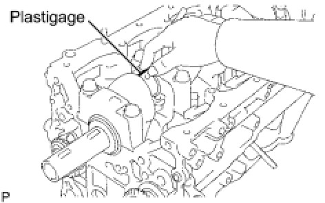
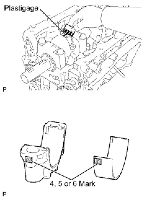
(f) Lay a strip of Plastigage on the crank pin.
(g) Check that the front mark of the connecting rod cap is facing forward.
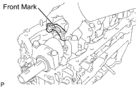
(h) Install the connecting rod cap.

NOTICE:
Do not turn the crankshaft.
(i) Remove the 2 bolts and connecting rod cap (see steps (b) and (c) above).
(j) Measure the Plastigage at its widest point.
Standard oil clearance:
0.024 to 0.049 mm (0.0009 to 0.0019 in.)
Maximum oil clearance:
0.066 mm (0.0026 in.)
If the oil clearance is greater than the maximum, replace the connecting rod bearings. If necessary, replace the crankshaft.
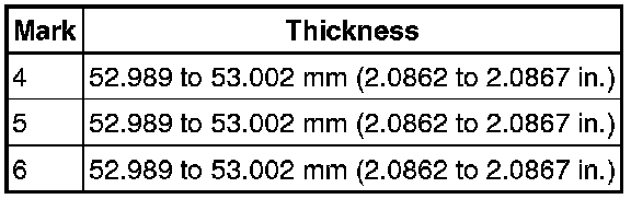
HINT
If replacing a bearing, replace it with one that has the same number as its respective connecting rod cap. Each bearing's standard thickness is indicated by a 1, 2 and 3 mark on its surface.
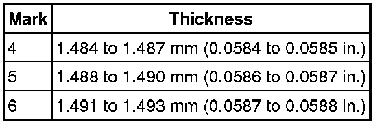
Reference:
Crankshaft pin diameter
Standard bearing center wall thickness
(k) Completely remove the Plastigage.
34. INSPECT CRANKSHAFT THRUST CLEARANCE
(a) Using a dial indicator, measure the thrust clearance while prying the crankshaft back and forth with a screwdriver.
Standard thrust clearance:
0.020 to 0.220 mm (0.0008 to 0.0087 in.)
Maximum thrust clearance:
0.30 mm (0.0118 in.)
If the thrust clearance is greater than the maximum, replace the thrust washers as a set. If necessary, replace the crankshaft.
Thrust washer thickness:
2.440 to 2.490 mm (0.0961 to 0.0980 in.)
35. CLEAN WITH PIN PISTON SUB-ASSEMBLY
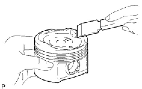
(a) Using a gasket scraper, remove the carbon from the piston top.
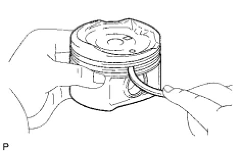
(b) Using a groove cleaning tool or broken ring, clean the piston ring grooves.
(c) Using solvent and a brush, thoroughly clean the piston.
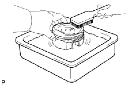
NOTICE:
Do not use a wire brush.
36. INSPECT NO. 1 OIL NOZZLE SUB-ASSEMBLY
(a) Check the oil nozzles for damage or clogging.
If necessary, replace the oil nozzle.
37. INSPECT BALANCE SHAFT THRUST CLEARANCE
(a) Using a dial indicator, measure the thrust clearance while moving the balanceshaft back and forth.
Standard thrust clearance:
0.07 to 0.13 mm (0.0027 to 0.0051 in.)
Maximum thrust clearance:
0.20 mm (0.0079 in.)
If the thrust clearance is greater than the maximum, replace the balanceshaft thrust washer. If necessary, replace the balanceshaft.
38. INSPECT CYLINDER BLOCK FOR FLATNESS
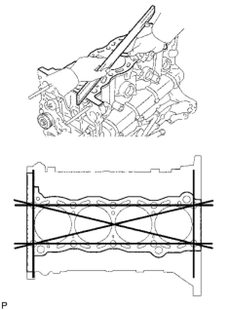
(a) Using a precision straight edge and feeler gauge, measure the warpage of the contact surface of the cylinder head gasket.
Maximum warpage:
0.05 mm (0.0020 in.)
If the warpage is greater than the maximum, replace the cylinder block.
(b) Visually check the cylinder for vertical scratches.
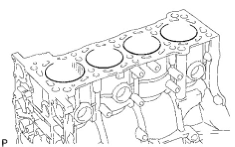
If deep scratches are present, rebore all the 4 cylinders. If necessary, replace the cylinder block.
39. INSPECT CYLINDER BORE
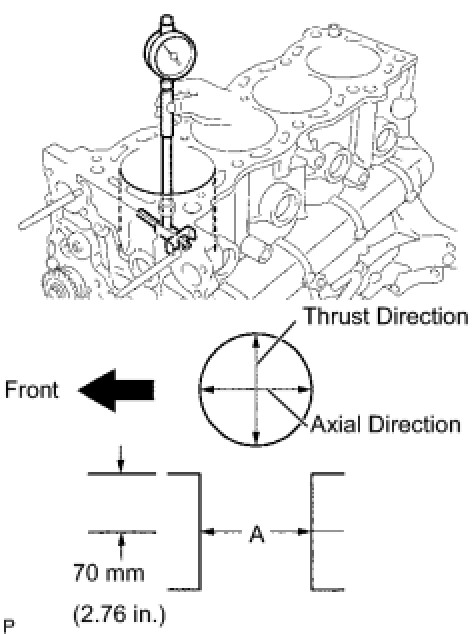
(a) Using a cylinder gauge, measure the cylinder bore diameter at positions A in the thrust and axial directions.
Standard diameter:
94.990 to 95.003 mm (3.7398 to 3.7403 in.)
Maximum difference diameter:
0.2 mm (0.008 in.)
If the diameter is greater than the maximum, rebore all the 4 cylinders. If necessary, replace the cylinder block.
(b) Inspect the cylinder ridge.
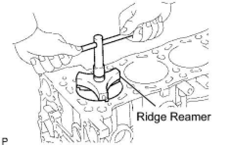
If the wear is less than 0.2 mm (0.008 in.), using a ridge reamer, grind the top of the cylinder.
40. CLEAN CYLINDER BLOCK
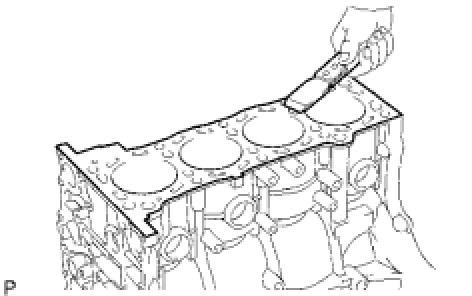
(a) Using a gasket scraper, remove all the gasket material from the top surface of the cylinder block.
(b) Using a soft brush and solvent, thoroughly clean the cylinder block.