Starter Signal Circuit
2TR-FE ENGINE CONTROL SYSTEM: SFI SYSTEM: Starter Signal Circuit
- Starter Signal Circuit
DESCRIPTION
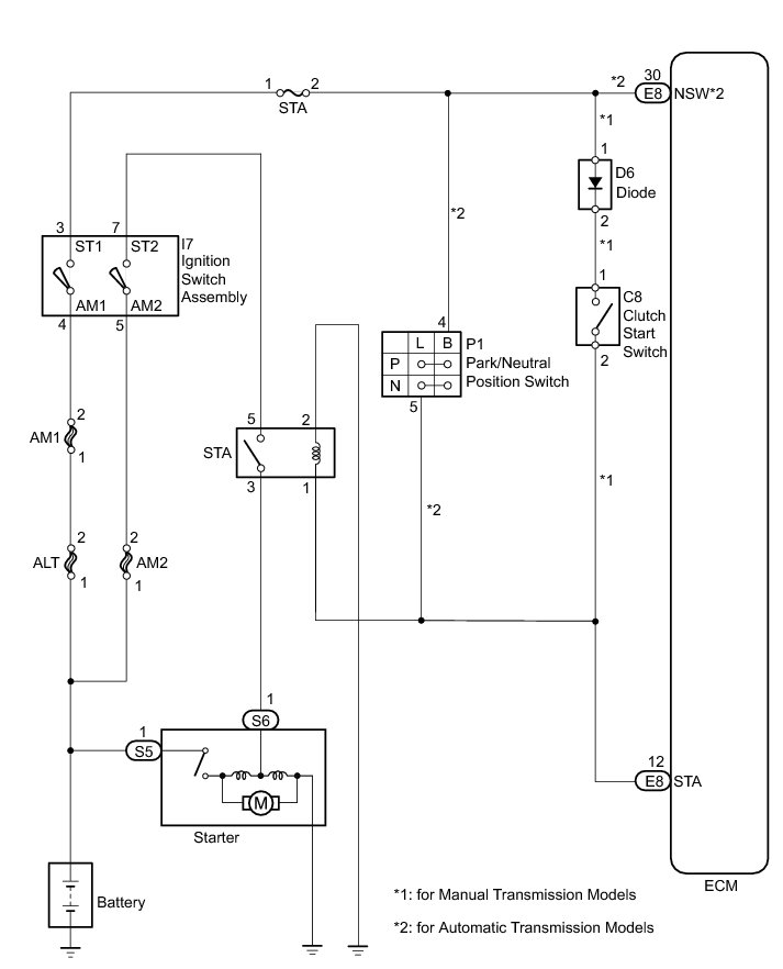
While the engine is being cranked, current flows from terminal ST1 of the ignition switch to the STA relay and also flows to terminal STA of the ECM (STA signal). The ECM uses the STA signal to control the fuel injection and ignition timing when the engine starts.
WIRING DIAGRAM
INSPECTION PROCEDURE
NOTICE:
Inspect the fuses for circuits related to this system before performing the following inspection procedure.
PROCEDURE
1. CHECK WHETHER ENGINE CAN BE CRANKED
(a) Check if the engine can be cranked.
Result
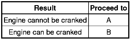
B -- READ VALUE USING TECHSTREAM (STARTER SIGNAL)
A -- Continue to next step.
2. READ VALUE USING TECHSTREAM (STARTER SIGNAL)
(a) Connect the Techstream to the DLC3.
(b) Turn the ignition switch to ON.
(c) Turn the Techstream on.
(d) Enter the following menus: Powertrain / Engine and ECT / Data List / Starter Signal.
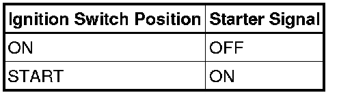
(e) Check the value displayed on the Techstream when the ignition switch is turned to the ON and START positions.
OK:
NG -- INSPECT IGNITION SWITCH ASSEMBLY
OK -- Continue to next step.
3. INSPECT IGNITION SWITCH ASSEMBLY
(a) Inspect the ignition switch assembly Testing and Inspection.
NG -- REPLACE IGNITION SWITCH ASSEMBLY Removal
OK -- Continue to next step.
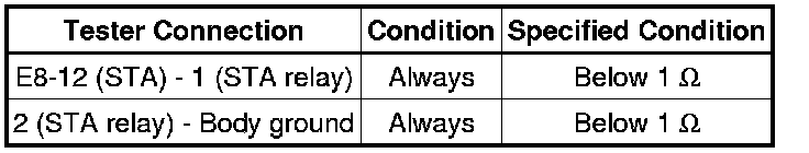
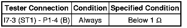
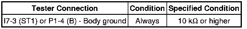
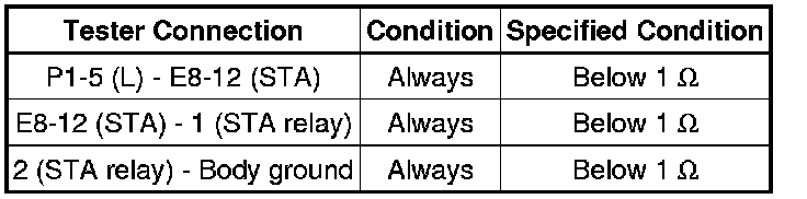
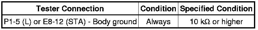
4. CHECK HARNESS AND CONNECTOR (IGNITION SWITCH ASSEMBLY - STA RELAY - STARTER)
(a) Remove the STA relay from the engine room relay block.
(b) Disconnect the ignition switch assembly connector.
(c) Disconnect the starter connector.
(d) Measure the resistance according to the value(s) in the table below.
Standard Resistance (Check for Open):
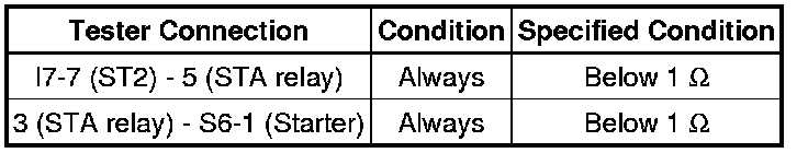
Standard Resistance (Check for Short):
NG -- REPAIR OR REPLACE HARNESS OR CONNECTOR
OK -- Continue to next step.
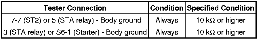
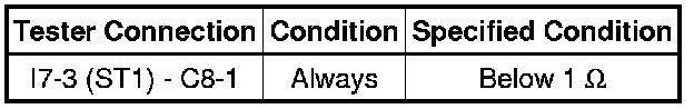
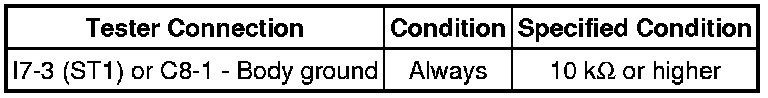
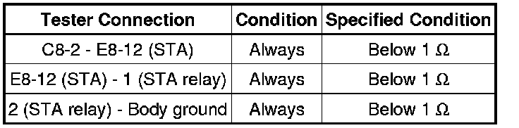
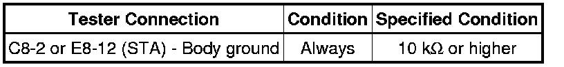
5. CHECK HARNESS AND CONNECTOR (ECM - STA RELAY - BODY GROUND)
(a) Remove the STA relay from the engine room relay block.
(b) Disconnect the ECM connector.
(c) Measure the resistance according to the value(s) in the table below.
Standard Resistance (Check for Open):
NG -- REPAIR OR REPLACE HARNESS OR CONNECTOR
OK -- PROCEED TO NEXT SUSPECTED AREA SHOWN IN PROBLEM SYMPTOMS TABLE Symptom Related Diagnostic Procedures
6. INSPECT IGNITION SWITCH ASSEMBLY
(a) Inspect the ignition switch assembly Testing and Inspection.
NG -- REPLACE IGNITION SWITCH ASSEMBLY Removal
OK -- Continue to next step.
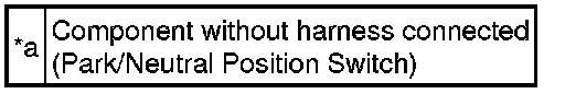
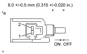
7. INSPECT PARK/NEUTRAL POSITION SWITCH OR CLUTCH START SWITCH
(a) Inspect the park/neutral position switch (for automatic transmission models).
(1) Disconnect the park/neutral position switch connector.
(2) Measure the resistance of the park neutral position switch when the transmission gear selector lever is moved to each position.
Standard Resistance:
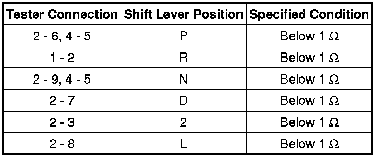
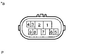
Text in Illustration
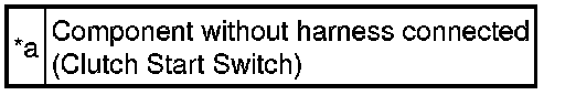
(b) Inspect the clutch start switch (for manual transmission models).
(1) Disconnect the clutch start switch connector.
(2) Measure the resistance between the terminals when the clutch start switch is ON and OFF.
Standard Resistance:
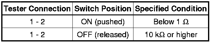
Text in Illustration
Result
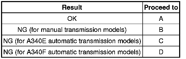
B -- REPLACE CLUTCH START SWITCH Removal
C -- REPLACE PARK/NEUTRAL POSITION SWITCH Removal
D -- REPLACE PARK/NEUTRAL POSITION SWITCH
A -- Continue to next step.
8. CHECK HARNESS AND CONNECTOR (IGNITION SWITCH ASSEMBLY - PARK/NEUTRAL POSITION SWITCH OR CLUTCH START SWITCH)
(a) For automatic transmission models:
(1) Disconnect the ignition switch assembly connector.
(2) Disconnect the park/neutral position switch connector.
(3) Measure the resistance according to the value(s) in the table below.
Standard Resistance (Check for Open):
Standard Resistance (Check for Short):
(b) For manual transmission models:
(1) Disconnect the ignition switch assembly connector.
(2) Disconnect the clutch start switch connector.
(3) Measure the resistance according to the value(s) in the table below.
Standard Resistance (Check for Open):
Standard Resistance (Check for Short):
NG -- REPAIR OR REPLACE HARNESS OR CONNECTOR
OK -- Continue to next step.
9. CHECK HARNESS AND CONNECTOR (STA RELAY - ECM - PARK/NEUTRAL POSITION SWITCH OR CLUTCH START SWITCH)
(a) For automatic transmission models:
(1) Remove the STA relay from the engine room relay block.
(2) Disconnect the ECM connector.
(3) Disconnect the park/neutral position switch connector.
(4) Measure the resistance according to the value(s) in the table below.
Standard Resistance (Check for Open):
Standard Resistance (Check for Short):
(b) For manual transmission models:
(1) Remove the STA relay from the engine room relay block.
(2) Disconnect the ECM connector.
(3) Disconnect the clutch start switch connector.
(4) Measure the resistance according to the value(s) in the table below.
Standard Resistance (Check for Open):
Standard Resistance (Check for Short):
NG -- REPAIR OR REPLACE HARNESS OR CONNECTOR
OK -- PROCEED TO NEXT SUSPECTED AREA SHOWN IN PROBLEM SYMPTOMS TABLE Symptom Related Diagnostic Procedures
10. READ VALUE USING TECHSTREAM (STARTER SIGNAL)
(a) Connect the Techstream to the DLC3.
(b) Turn the ignition switch to ON.
(c) Turn the Techstream on.
(d) Enter the following menus: Powertrain / Engine and ECT / Data List / Starter Signal.
(e) Check the value displayed on the Techstream when the ignition switch is turned to the ON and START positions.
OK:

NG -- CHECK HARNESS AND CONNECTOR (ECM - STA RELAY)
OK -- PROCEED TO NEXT SUSPECTED AREA SHOWN IN PROBLEM SYMPTOMS TABLE Symptom Related Diagnostic Procedures
11. CHECK HARNESS AND CONNECTOR (ECM - STA RELAY)
(a) Remove the STA relay from the engine room relay block.
(b) Disconnect the ECM connector.
(c) Measure the resistance according to the value(s) in the table below.
Standard Resistance (Check for Open):
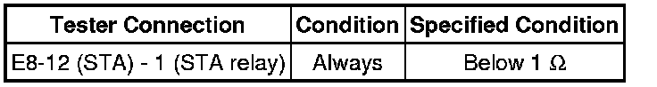
NG -- REPAIR OR REPLACE HARNESS OR CONNECTOR
OK -- REPLACE ECM Removal