How To Use This Information
HOW TO USE THIS INFORMATIONThis provides information on the electrical circuits installed on vehicles by dividing them into a circuit for each system.
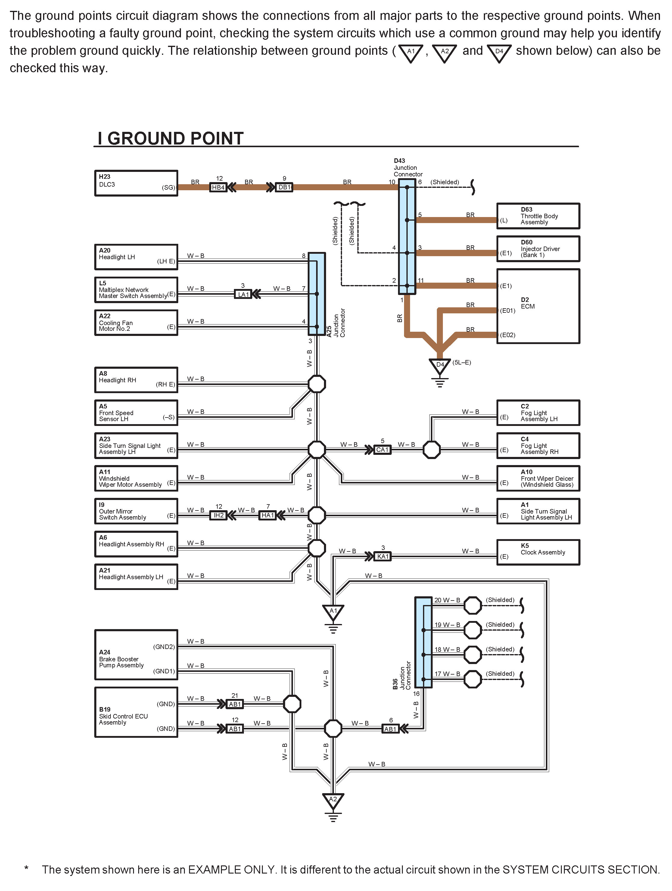
The actual wiring of each system circuit is shown from the point where the power source is received from the battery as far as each ground point. (All circuit diagrams are shown with the switches in the OFF position.)
When troubleshooting any problem, first understand the operation of the circuit where the problem was detected, the power source supplying power to that circuit, and the ground points.
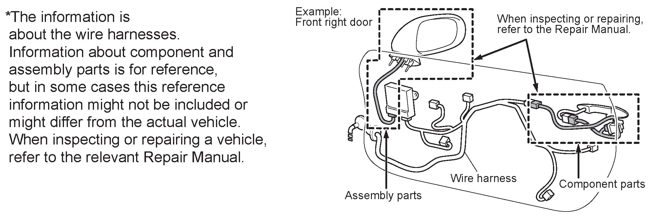
When the circuit operation is understood, begin troubleshooting of the problem circuit to isolate the cause. Use Relay Location and Electrical Wiring Routing sections to find each part, junction block and wiring harness connectors, wiring harness and wiring harness connectors and ground points of each system circuit. Internal wiring for each junction block is also provided for better understanding of connection within a junction block.
Wiring related to each system is indicated in each system circuit by arrows (from__, to__). When overall connections are required, see the Overall Electrical Wiring Diagram.
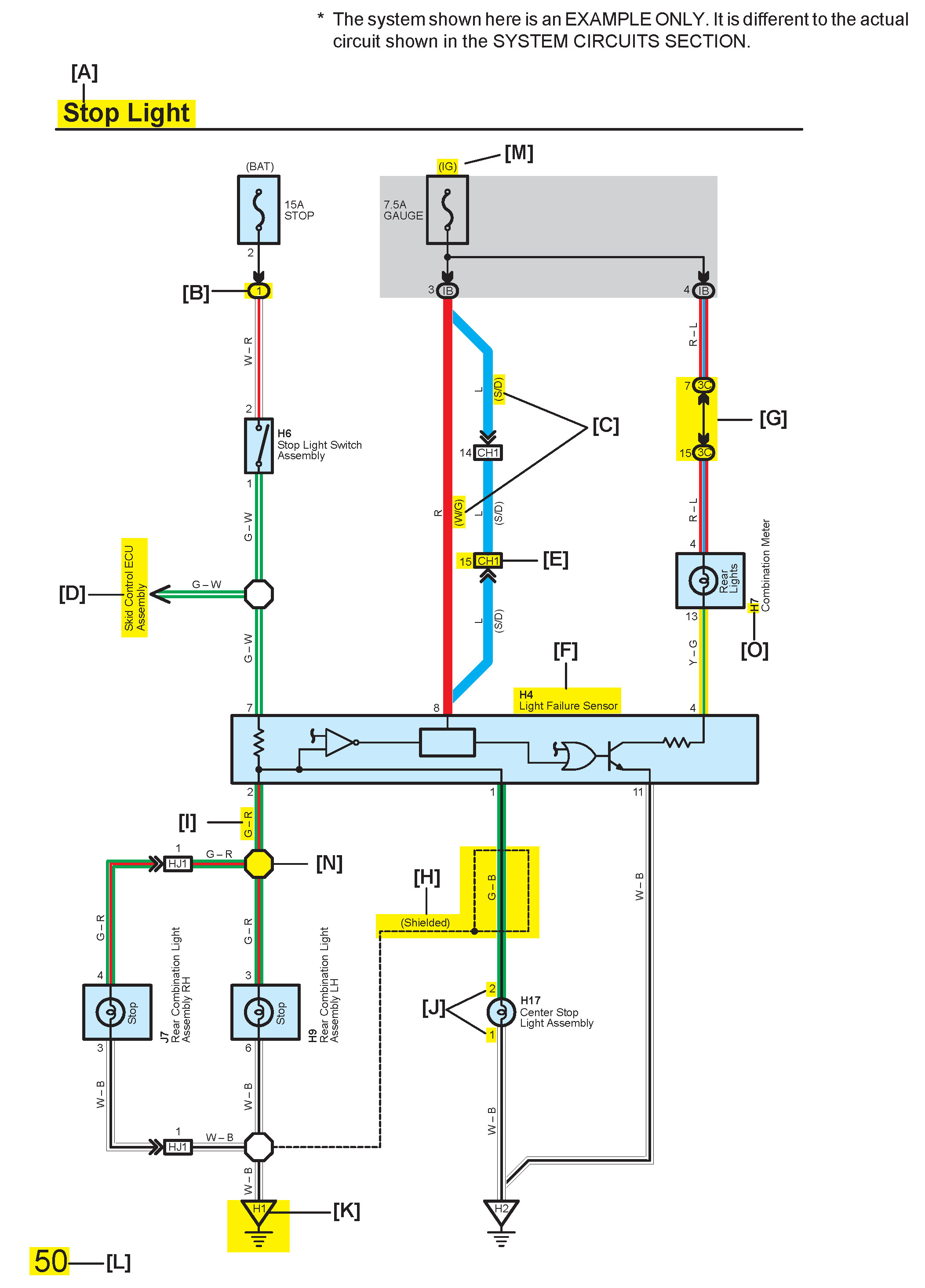
[A] : System Title
[B] : Indicates a Relay Block. No shading is used and only the Relay Block No. is shown to distinguish it from the J/B
Example: (1) Indicates Relay Block No.1
[C] : ( ) is used to indicate different wiring and connector, etc. when the vehicle model, engine type, or specification is different.
[D] : Indicates related system.
[E] : Indicates the code for the (male and female) connectors which are used to join two wire harnesses. The connector code consists of two alphabetical and one numerical characters.
The first character of the connector code indicates the alphabetical code allocated to the wire harness which has the female connector, and the second shows that of the wire harness which has the male connector.
The third character indicates a serial number used to distinguish between the wire harness combinations in cases when more than one of the same combination of wire harnesses exist (e.g. CH1 and CH2).
Symbol (down arrow) indicates the male terminal connector. Numbers outside connector codes indicate the pin numbers of both male and female connectors.
[F] : Represents a part (all parts are shown in sky blue). The code is the same as the code used in parts position.
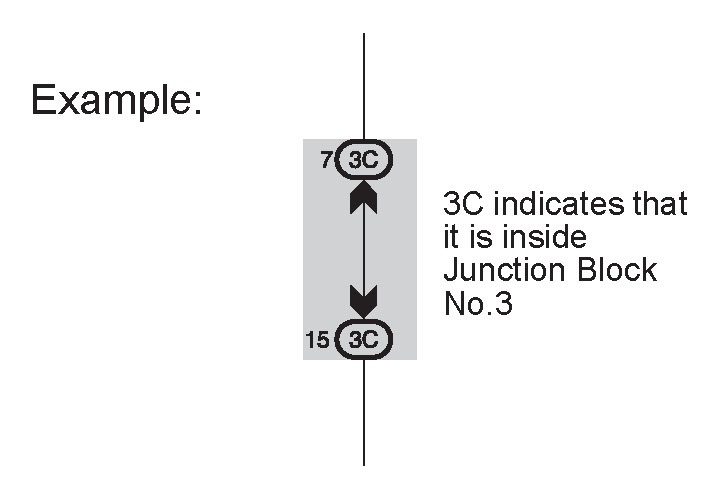
[G] : Junction Block (The number in the circle is the J/B No. and the connector code is shown beside it). Junction Blocks are shaded to clearly separate them from other parts.
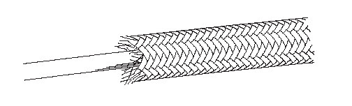
[H] : Indicates a shielded cable.
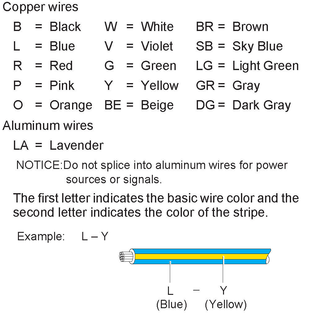
[I] : Indicates the wiring color.
Wire colors are indicated by an alphabetical code.
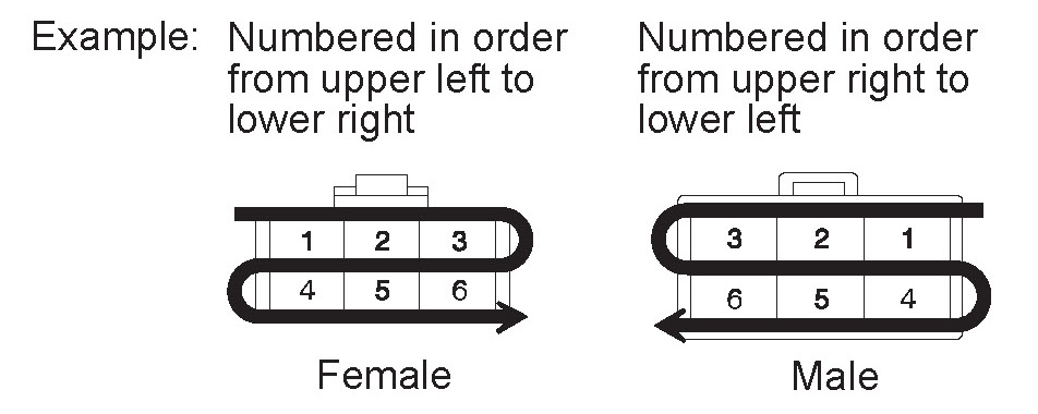
[J] : Indicates the pin number of the connector. The numbering system is different for female and male connectors.
[K] : Indicates the ground point. The code consists of the two characters: A letter and number.
The first character of the code indicates the alphabetical code allocated to the wire harness. The second character indicates a serial number used to distinguish between the ground points in cases when more than one ground point exist on the same wire harness.
[L] : Page No.
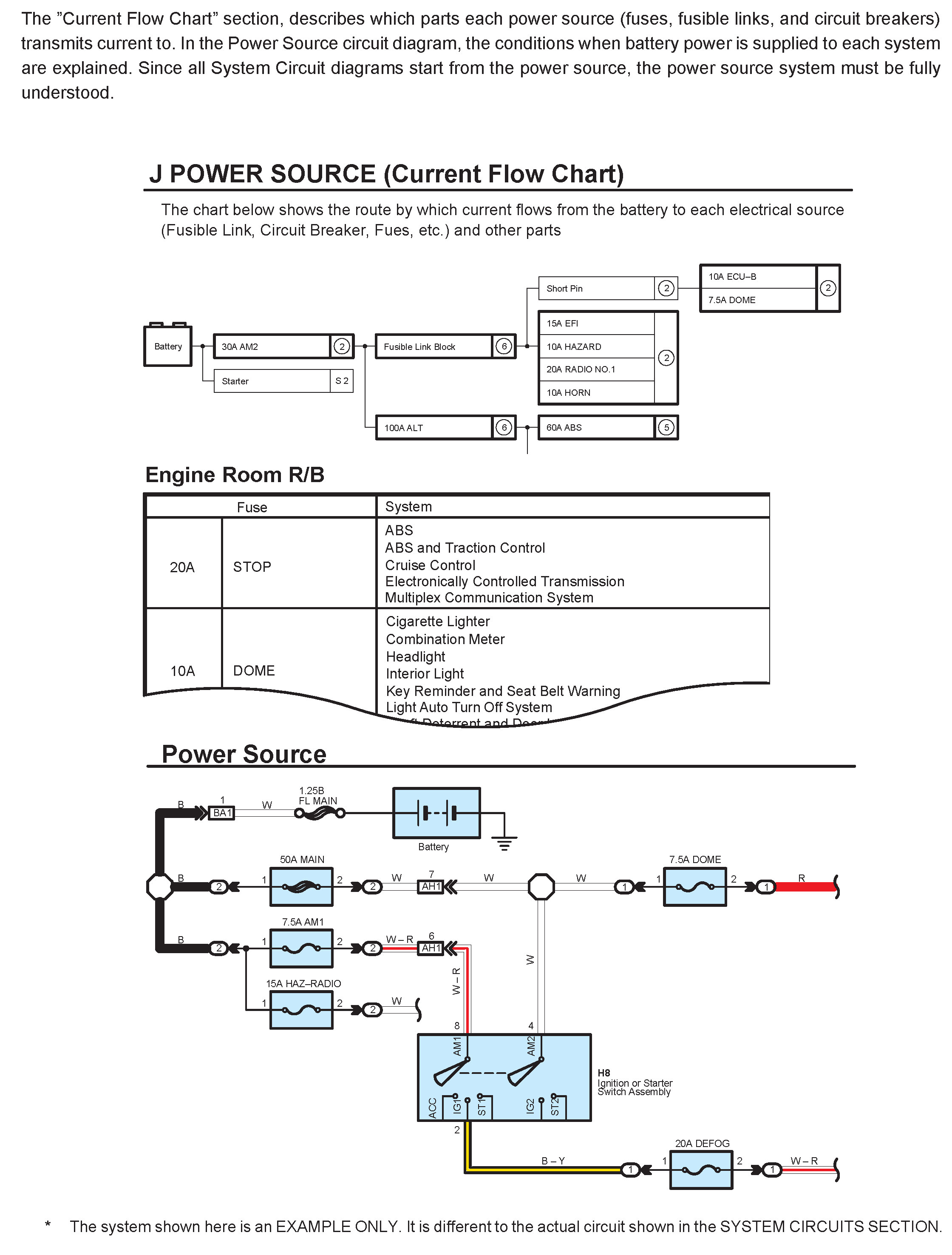
[M] : Indicates the ignition key position(s) when the power is supplied to the fuse(s).
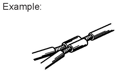
[N] : Indicates a wiring Splice Point.
[O] : Wire Harness Code
Each wire harness is represented by a code. Wire harness codes are used in the parts codes, connector joining wire harness and wire harness codes, and ground point codes. For example, H7 (combination meter), CH1 (male, connector joining wire harness and wire harness), and H2 (ground point) indicate that they are the parts belonging to the same wire harness "H".
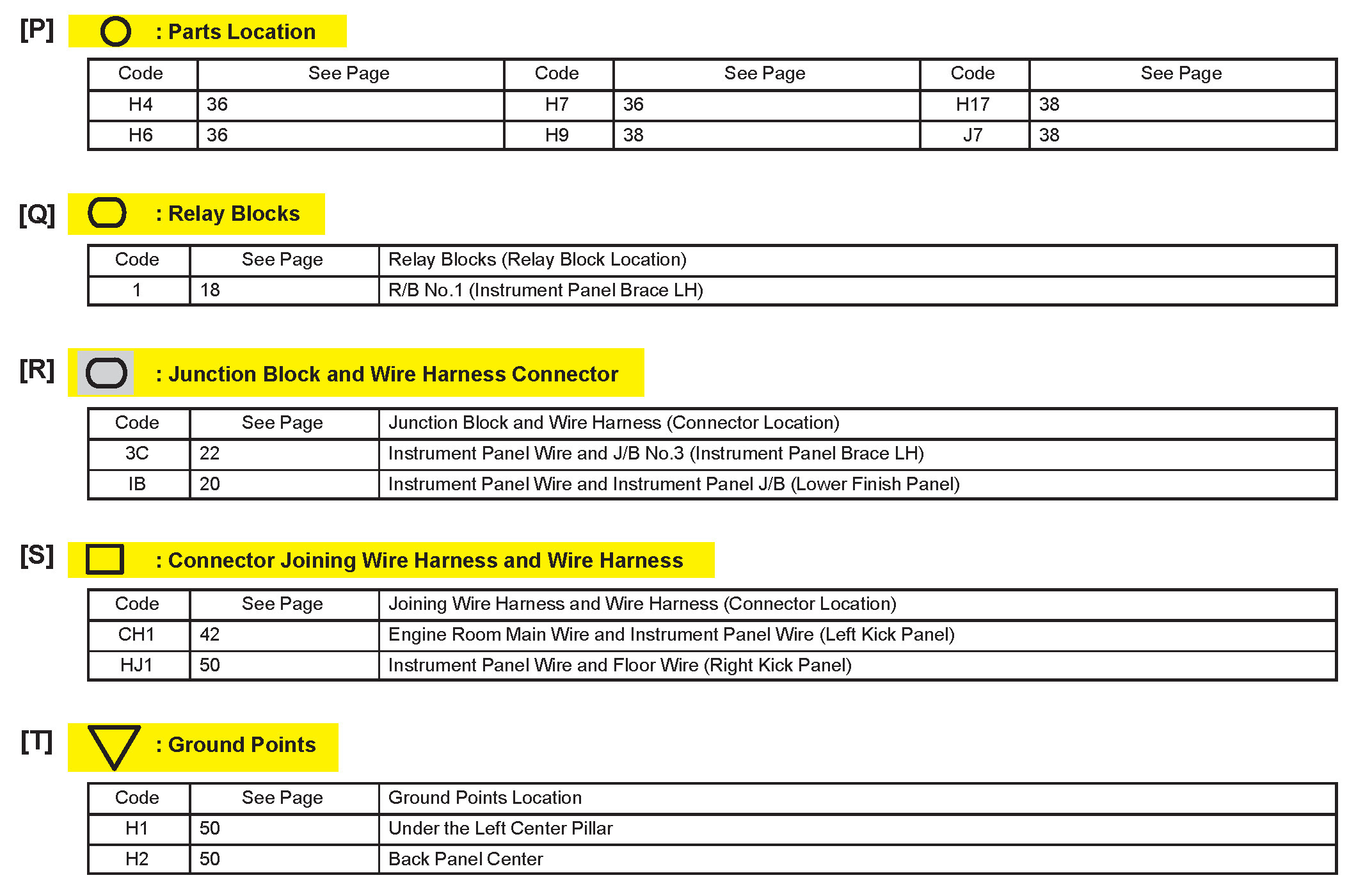
[P] : Indicates reference showing the parts locations in the system circuit on the vehicle.
Example : Code "H4" (Light Failure Sensor)
* The first character of the code indicates the alphabetical code allocated to the wire harness, and the second character indicates the serial number of the parts connected to the wire harness.

[Q] : Indicates the reference showing the position on the vehicle of Relay Block Connectors in the system circuit.
Example : Connector "1" is described and is installed on the left side of the instrument panel.
[R] : Indicates the reference showing the position on the vehicle of J/B and Wire Harness in the system circuit.
Example : Connector "3C" connects the Instrument Panel Wire and J/B No.3. It is described and is installed on the instrument panel left side.
[S] : Indicates the reference describing the wiring harness and wiring harness connector (the female wiring harness is shown first, followed by the male wiring harness).
Example : Connector "CH1" connects the Engine Room Main Wire (female) and Instrument Panel Wire (male). It is described and is installed on the left side kick panel.
[T] : Indicates the reference showing the position of the ground points on the vehicle.
Example : Ground point "H2" is described installed on the back panel center.
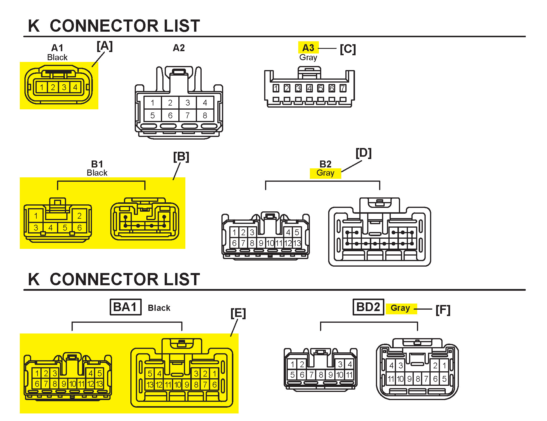
[A] : Indicates connector to be connected to a part. (The numeral indicates the pin No.)
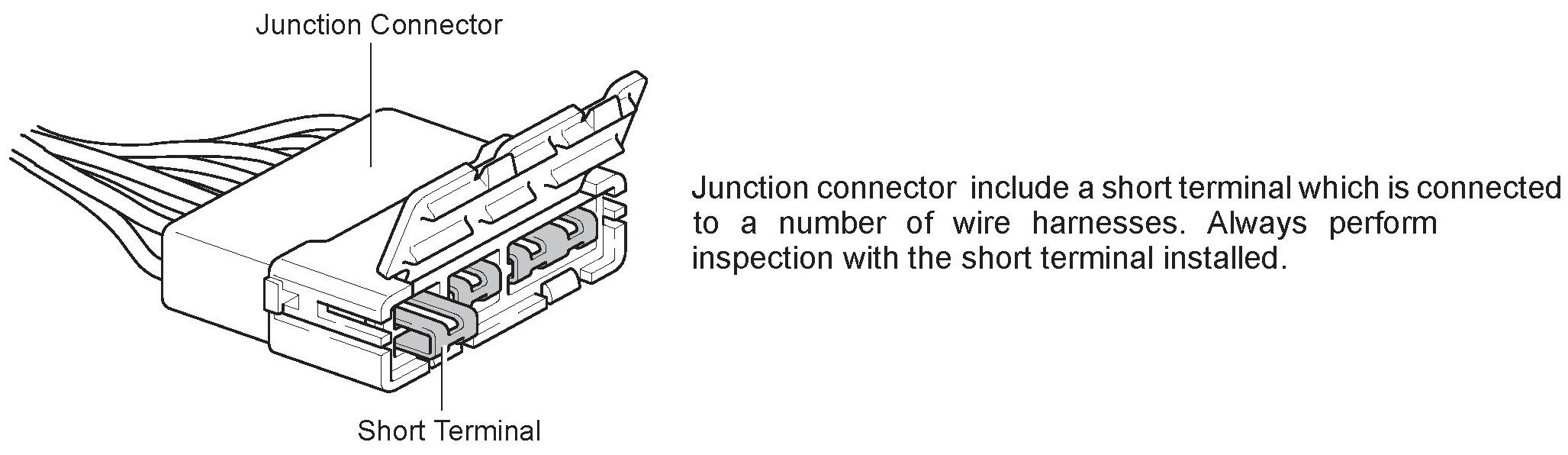
[B] : Junction Connector
Indicates a connector which is connected to a short terminal.
[C] : Parts Code
The first letter of the code is taken from the first letter of part, and the numbers indicates its order in parts which start with the same letter.
[D] : Connector Color
Connectors not indicated are milky white in color.
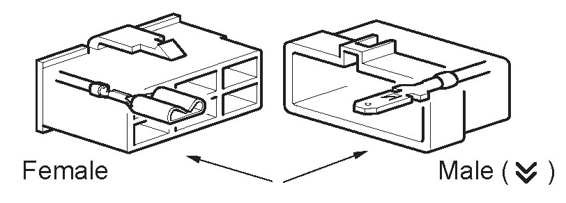
[E] : Indicates the connector shapes which are used to join wire harnesses.
On Left : Female connector shapes
On Right : Male connector shapes
Numbers indicate pin numbers.
[F] : Indicates connector colors. (Connectors with not indicated colors are white)