Reconditioning
DISASSEMBLY, ASSEMBLY, AND RECONDITIONING:- Disassembly, assembly, and reconditioning procedures for the cylinder heads used on Volkswagen engines are similar to those for most other modern 4-cylinder, water-cooled engines with alloy cylinder heads. For anyone with the proper tools and equipment and basic experience in cylinder head reconditioning, this section provides the reconditioning information necessary to repair these Volkswagen engines.
- Cylinder head reconditioning is not overly complicated, but it does require a variety of special equipment and skills. For those who are without the necessary tools, or unfamiliar with reconditioning procedures, this work may be best left to a professional automotive machinist. You will still find this information to be important to the qualified machinist who does the work. If machine shop services are not readily available, one alternative is to install a Volkswagen remanufactured cylinder head, available from an authorized Volkswagen dealer parts department.
Cylinder Head Assembly:
Cylinder Head, Exploded View:

- Cylinder heads with small fine cracks between valve seats and plug threads are usable provided the cracks are not more than 0.5 mm (0.02 in.) wide and do not extend into more than the first few spark plug threads.
Camshaft Axial Clearance:
Checking Camshaft Axial Play:
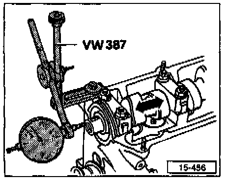
- The image above shows a dial indicator setup used to check axial or end-to-end thrust clearance.
- To measure camshaft axial play, relieve the tension on the cam lobes by first removing the cam followers. Then reinstall end caps only.
NOTE: Store hydraulic cam followers with the camshaft contact surface face down.
- Camshaft axial clearance (wear limit): 0.15 mm (0.006 in.).
- Lubricate the cam follower's contact surfaces before installing.
NOTE: Do not interchange camshaft bearing caps or cam followers. Note the bearing cap offset when installing.
Camshaft Radial Clearance:
- Check camshaft radial clearance, bearing clearance measured perpendicular to the camshaft, using Plastigage (R) or its equivalent.
- Remove valve lifters.
- Clean camshaft and cylinder head bearing surfaces.
- Make sure the camshaft lobes are not touching the hydraulic cam followers.
CAUTION: Do not turn the camshaft while the Plastigage (R) is in place. Remove all traces of Plastigage (R) from the cam journals and bearing surfaces before final assembly.
- Camshaft radial clearance (wear limit): 0.11 mm (0.0043 in.).
- Bearing cap tightening torque: 20 Nm (15 ft lb).
Valves:
- Valves cannot be refaced by machine. They must always be hand-lapped only.
Valve Guides:
Checking Valve Guide Wear:

- To properly recondition a worn cylinder head, the valve guides must be checked for wear. Valve guides should be replaced if necessary before machining the valve seats.
- Check valve guides for wear by inserting a new valve and measuring side-to-side play. The valve should be inserted just far enough so that the end of the valve stem is flush with the guide.
NOTE: There are slight size differences between the intake and exhaust guides. Use only intake valves to check intake guides, and exhaust valves for exhaust guides.
- Valve guide maximum play:
Intake: 1.0 mm (0.039 in.).
Exhaust: 1.3 mm (0.059 in.).
- Original valve guides, without shoulders, are pressed out from the camshaft side of the cylinder head. Replacement valve guides, with shoulders, are pressed out from the combustion chamber side of the cylinder head. Lubricate new valve guides with oil and press them in from the camshaft side. Remove and install guides with Volkswagen special tool no. 10-206 (order no. T10 206 000 15 ZEL).
Valve Seats:
- There is a limit to how much material can be removed when refacing valve seats. If the valve seats are cut too far, the final assembly will leave too little space for the hydraulic lifter to function properly. A calculation must be made before refacing the valve seats.
Minimum Dimension For Calculating Valve Seat Refacing Dimension:
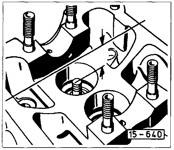
- Measure the distance between top of valve stem and top (gasket) surface of cylinder head, with the valve firmly seated, as shown in the image above. Then subtract the minimum dimension as listed below. The difference is the maximum allowable depth of cut for refacing. Remove only as much material as is required to get an acceptable seat.
- Minimum Dimension (valve stem to head):
Intake: 33.8 mm (1.331 in.).
Exhaust: 34.1 mm (1.343 in.).