Air Flow Meter/Sensor: Testing and Inspection
Mass Air Flow sensor, checking
Special tools, testers, measuring instruments and auxiliary items required
- VAG 1551/1552 Scan Tool with VAG 1551/3B adaptor cable
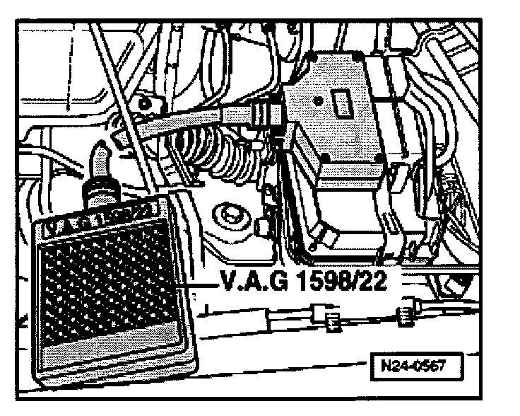
- VAG 1598/22 Test Box
- Fluke 83 Multimeter
- VW 1594 Adaptor kit
- Wiring diagram
Check conditions
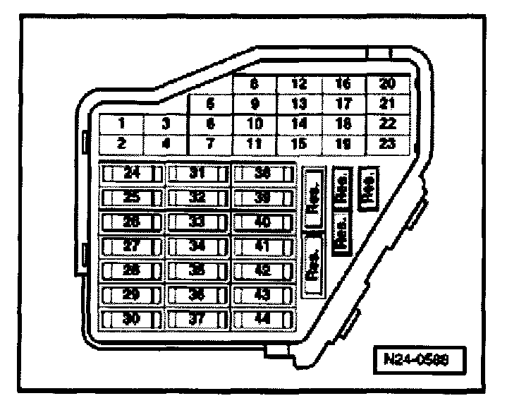
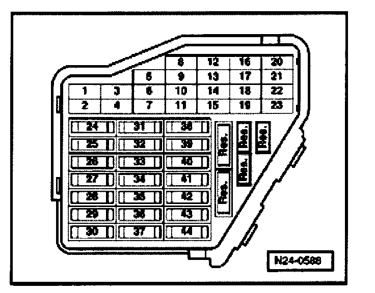
- Fuse 29 OK.
- Engine Coolant Temperature must be at least 85 °C, = Display group 04, Display zone 3
- All electrical consumers, e.g. lights and rear window defroster must be switched OFF
- A/C switched OFF (if installed).
- Transmission Range selector lever in "P" or "N" position (automatic transmission only)
Test sequence
- Connect VAG 1551/1552 Scan Tool, [1][2][3]Reading and Clearing Diagnostic Trouble Codes
- Start engine and let idle
- Press 0 and 1 buttons to select "Address word" 01 "Engine electronics"
Display will appear as shown
Rapid data transfer HELP
Select function XX
- Press 0 and 8 buttons to select Function 08: "Read measuring value block"
- Press Q button to enter input
Display will appear as shown
Read measuring value block HELP
Input Display group number XXX
- Press 0, 0 and 2 buttons to select "Display group 2"
- Press Q button to enter input
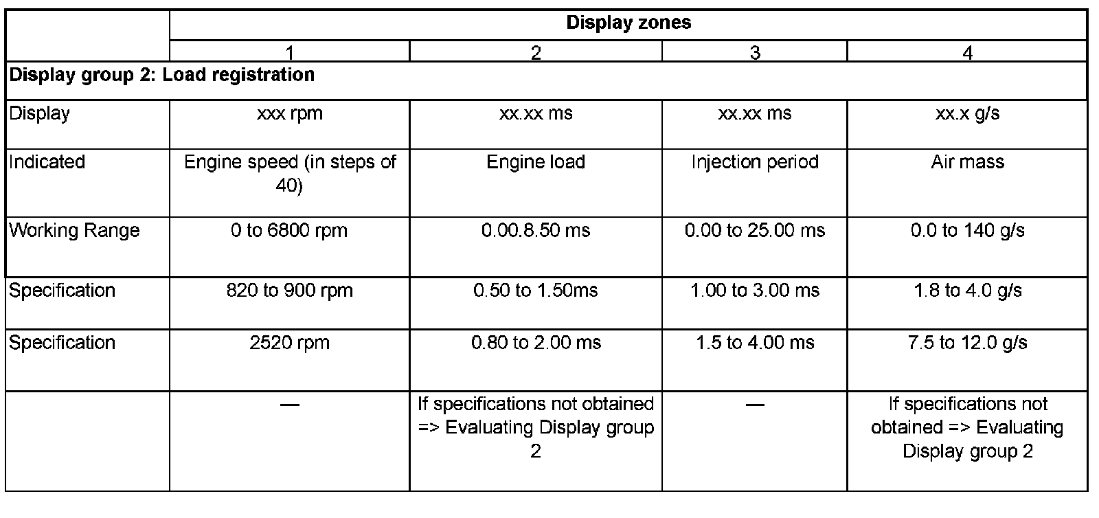
Display will appear as shown (1 to 4 = Display zones)
Read measuring value block 2 ->
1 2 3 4
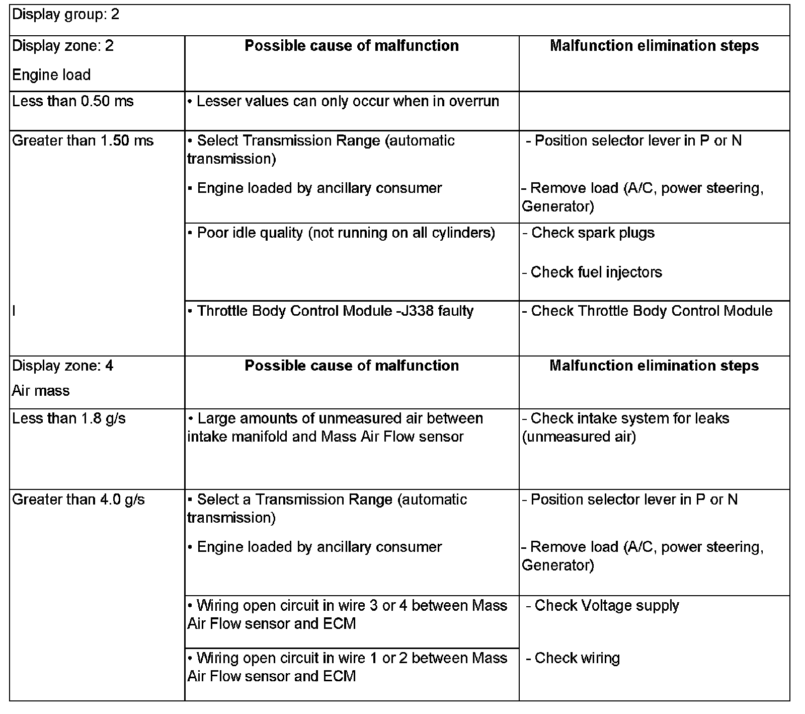
- Check the load registration specifications (Display zones 2 and 4 on chart)
- Press -> button.
- Press 0 and 6 buttons to select Function 06: "End data output"
- Press Q button to enter input
- Switch OFF ignition.
If the specifications are not obtained or there is a DTC stored in DTC memory related to the Mass Air Flow sensor:
- Check Mass Air Flow sensor Voltage supply as follows:
Voltage supply, checking
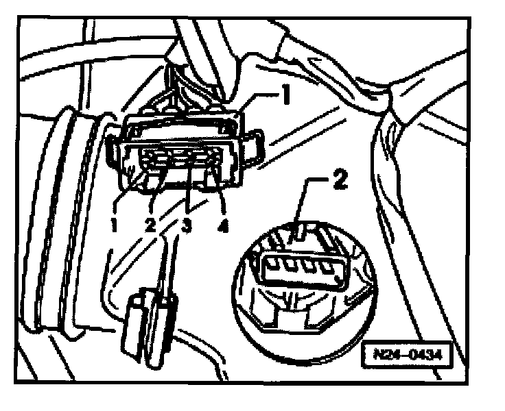
- Disconnect 4-pin harness connector -1- from Mass Air Flow sensor -2-.
- Switch Multimeter to Voltage range
- Connect Multimeter between connector terminals 1 and 3.
- Start engine and let idle.
- Specification: 11 to 15 Volts
- Switch OFF ignition.
If Voltage supply OK
- Test signal and Ground wires.
If NO Voltage present:
- Check wiring between terminal 3 to fuel pump relay J17 using Wiring diagram.
Signal wire, checking
- Connect VAG 1598/22 Test Box to ECM wiring harness.
- Check wiring for open circuit between Test Box and 4-pin harness connector using Wiring diagram.
Terminal 4 + socket 13
Terminal 2 + socket 12
Wire resistance: Max. 1.5 Ohms
- Check wiring for open circuit between 4-pin harness connector and Ground using Wiring diagram.
Terminal 1 + Ground
Wire resistance: Max. 1.5 Ohms
- Remove fuse 28.
- Check all wires for shorting to one another.
Specification: Infinity Ohms
NOTE: If fuse 28 is not removed the fuel pump will short circuit between connector terminals 1 + 3.
If wiring OK
- Replace Mass Air Flow sensor G70.
Evaluating Display group 2