Engine Coolant Temperature (ECT) Sensor, Checking
Engine Coolant Temperature sensor, checking
Special tools, testers, measuring instruments and auxiliary items required
- VAG 1551/1552 Scan Tool with VAG 1551/3B adaptor cable
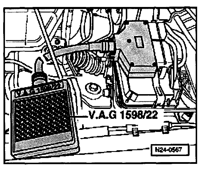
- VAG 1598/22 Test Box
- Fluke 83 Multimeter
- VW 1594 Adaptor kit
- Wiring diagram
NOTE: The Engine Control Module will use the Intake Air Temperature as a replacement value for an engine start (start temperature replacement value) as soon as there is a DTC stored in DTC memory, which affects the Engine Coolant Temperature sensor G62. The temperature then rises using a model stored in the Control Module. When the engine has reached normal working temperature a fixed replacement value will be displayed after a certain period. This fixed value is also dependent upon the Intake Air Temperature.
Test conditions
- Engine must be cold.
Test sequence
- Connect VAG 1551/1552 Scan Tool, [1][2][3]Reading and Clearing Diagnostic Trouble Codes
- Switch ON ignition
- Press 0 and 1 buttons to select "Address word" 01 "Engine electronics"
Display will appear as shown
Rapid data transfer HELP
Select function XX
- Press 0 and 8 buttons to select Function 08: "Read measuring value block"
- Press Q button to enter input
Display will appear as shown
Read measuring value block HELP
Input Display group number XXX
- Press 0, 0 and 1 buttons to select "Display group 1"
- Press Q button to enter input
Display will appear as shown (1 to 4 = Display zones)
Read measuring value block 1 ->
1 2 3 4
- Check the specification for Engine Coolant Temperature sensor in Display zone 2, chart.
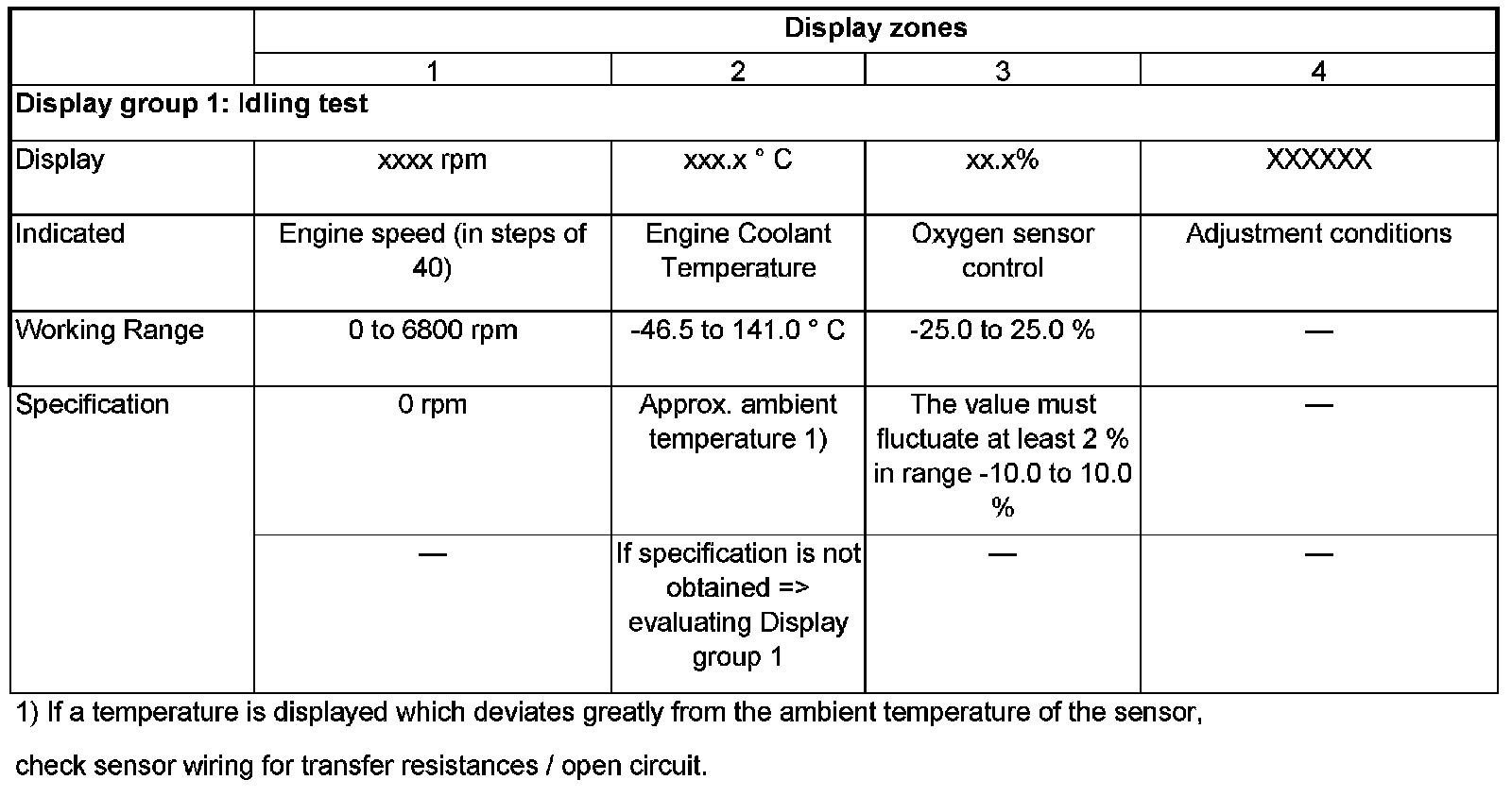
Continuation:
- Start engine and let idle.
- Engine Coolant Temperature value must increase uniformly
If specification not obtained
- Replace Engine Coolant Temperature sensor G62.
- Press -> button.
- Press 0 and 6 buttons to select Function 06: "End data output"
- Press Q button to enter input
- Switch OFF ignition.
NOTE:
- Display on Scan Tool increments in 1.5 °C steps.
- If irregular engine running occurs in certain temperature ranges and the temperature figure does not increase without interruption, the temperature signal is temporarily interrupted and the sensor must be replaced.
Evaluating Display group 1
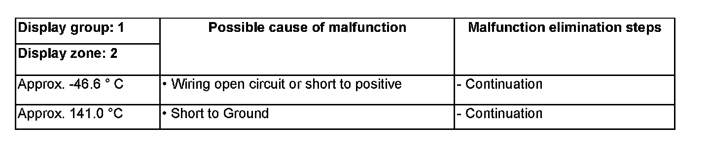
Continuation of check when Display approx. - 46 °C:
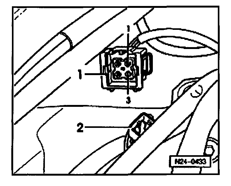
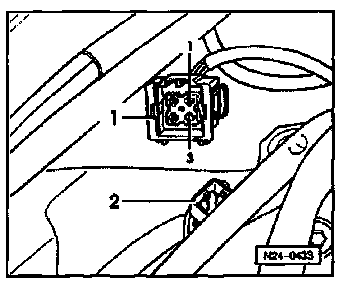
- Disconnect 4-pin harness connector -1- from Engine Coolant Temperature sensor G62 -2-
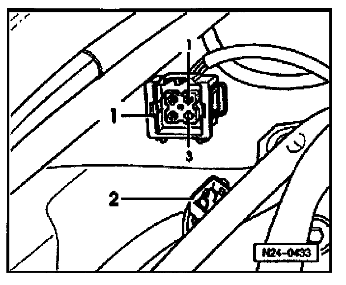
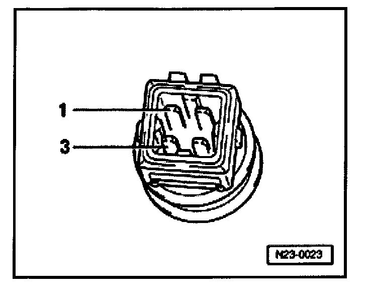
- Bridge connector terminals 1 + 3 using jumper wires from W 1594 adaptor kit and observe display.
When Display is approx. 141 ° C:
- Press -> button.
- Press 0 and 6 buttons to select Function 06: "End data output"
- Press Q button to enter input
- Switch OFF ignition.
- Replace Engine Coolant Temperature sensor G62.
When Display is approx. - 46 °C:
- Press -> button.
- Press 0 and 6 buttons to select Function 06: "End data output"
- Press Q button to enter input
- Switch OFF ignition.
- Check wiring using Wiring diagram.
Continuation of check when Display approx. 141 °C:
- Disconnect 4-pin harness connector -1- from Engine Coolant Temperature sensor G62 -2-
When Display is approx. -46 °C:
- Press -> button.
- Press 0 and 6 buttons to select Function 06: "End data output"
- Press Q button to enter input
- Switch OFF ignition.
- Replace Engine Coolant Temperature sensor G62.
When Display is approx. 141 °C:
- Press -> button.
- Press 0 and 6 buttons to select Function 06: "End data output"
- Press Q button to enter input
- Switch OFF ignition.
- Check wiring using Wiring diagram.
Wiring, checking
- Connect VAG 1598/22 Test Box to Control Module harness connector.
- Disconnect 4-pin harness connector -1- from Engine Coolant Temperature sensor G62 -2-
- Check wire for open circuit between Test Box socket 67 and 4-pin harness connector terminal 3 using Wiring diagram.
- Wire resistance: Max. 1.5 Ohms
- Check wire for open circuit between Test Box socket 53 and 4-pin harness connector terminal 1 using Wiring diagram.
- Wire resistance: Max. 1.5 Ohms
- Check 4-pin connector wires for short using Wiring diagram.
- Terminal 1 + Test Box socket 67
- Terminal 1 + vehicle Ground
- Specification: Infinity Ohms
- Check both wires for short to Battery +.
- Specification: Infinity Ohms
If wiring OK
- Perform resistance measurement at Engine Coolant Temperature sensor G62 terminal 1 (signal) and 3 (Ground).
Scale A shows resistance values for temperature range 0 to 50 °C and scale B the values for temperature range 50 to 100 °C.
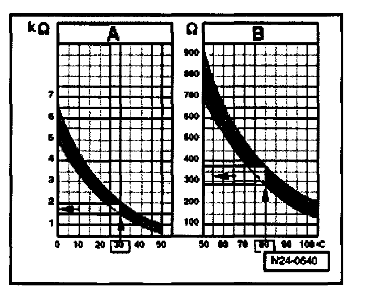
Examples:
- 30 °C is in range A and corresponds to 1.5 to 2.0 k Ohms
- 80 °C is in range B and corresponds to 275 to 375 Ohms
If specification not obtained
- Replace Engine Coolant Temperature sensor G62.
If wiring OK and resistance measurement values OK
- Replace Engine Control Module.
NOTE: If DTC memory has been erased or the Engine Control Module was disconnected from its Voltage supply, the Readiness Code must be created again , Monitors, Trips, Drive Cycles and Readiness Codes