Instrument Panel, Removing and Installing
Instrument Panel, Removing And Installing
Removing
- Disconnect vehicle battery.
- Remove center console.
- Remove driver side airbag unit.
- Remove steering wheel.

- Unscrew 2 Phillips-head bolts - arrows -.
- Remove upper trim for steering column switches - 1 -.

- Unscrew Phillips-head bolts - arrows -.
- Remove hex socket head bolt - 1 -.
- Loosen height adjustment for steering wheel - 2 -.
- Remove lower trim for steering column switch - 3 -.

- Remove socket head bolt - 1 -.
- Disconnect harness connectors - arrows - from steering column switch.
- Remove steering column switches - 2 -.
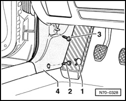
- Pry off cap - 1 -.
- Remove bolts - 2 - and - 3 -.
- Unclip lower A-pillar trim on drivers side - 4 - from sill trim and remove.

- Unclip cover - 1 -.
- Remove bolts - arrows -.
- Remove storage compartment on drivers side - 2 -.
- Disconnect harness connectors from light switch - 3 - and from headlight beam adjuster - 4 -.

- Slide cover - 1 - upward and clamp using equipment (e.g. screwdriver handle) - 2 -.
- Remove four bolts - arrows -.
- Remove cover - 3 -.

- Remove two bolts - arrows -.
- Remove instrument cluster.
- Disconnect harness connectors.

- Remove two bolts - arrows -.
Radio Removal Tool required for removing the radio.
Radio Removal Tool consists of two equivalent individual parts.

- Slide Radio Removal Tool into release slots - arrows - until they engage.
- Pull radio out of instrument panel using grip rings on removal tool.
NOTE:
- Radio Removal Tool must not be pushed to the side or tilted during procedure.
- To remove removal tool from radio, press in locking lugs on side of radio.
- Disconnect harness connectors.

- Unclip trim - 1 -.

- Remove 8 bolts - arrows -.
- Pull out cover for center instrument panel - 1 - and disconnect harness connectors.

- Remove five bolts - arrows -.

- Disengage three clips - arrows - using flat screwdriver - 1 -.
NOTE: The locking mechanism is located in the upper area of juncture between vent and instrument panel.
- Keep vent - 2 - under load while doing so, to prevent disengaged clips from engaging again.
- Pull vent - 2 - out of instrument panel and disconnect harness connector - 3 -.

- Remove bolt - arrow -.
- Remove trim - 1 -.

- Pry off cap - 1 -.
- Remove bolts - 2 - and - 3 -.
- Unclip lower A-pillar trim on passengers side - 4 - from sill panel and remove.

- Remove bolts - arrows -.
- Open storage compartment on passengers side - 1 -.

- Carefully unclip light at top from locking mechanism using screwdriver.
NOTE: Be careful not to damage glove compartment lamp switch when removing lamp.
- Carefully remove diffusion lens with lamp holder.
- Replace 12V/3W lamp if necessary.
NOTE:
- Note installation position of glove compartment lamp when installing. Storage compartment switch must point downward.
- For the sake of illustration, glove compartment is depicted as removed.

- Install diffusion lens with mounting plate into storage compartment and engage.
After repair work of glove compartment lamp, a function test of switch must be performed. Lamp must not light up with cover closed.

- Remove bolts - arrows -.
- Disconnect harness connector - 2 - from lamp - 1 -.

- Pull storage compartment on passengers side - 1 - out of instrument panel - arrow -.

- Pry off cover - 1 -.

- Remove hex bolts - arrows -.
- Disconnect harness connector - 1 -.
- Remove instrument panel.
Installing
Installation is the reverse order of removal.