With Generic Scan Tool
Checking fuel injectors for injection quantity and proper seal
Recommended special tools and equipment
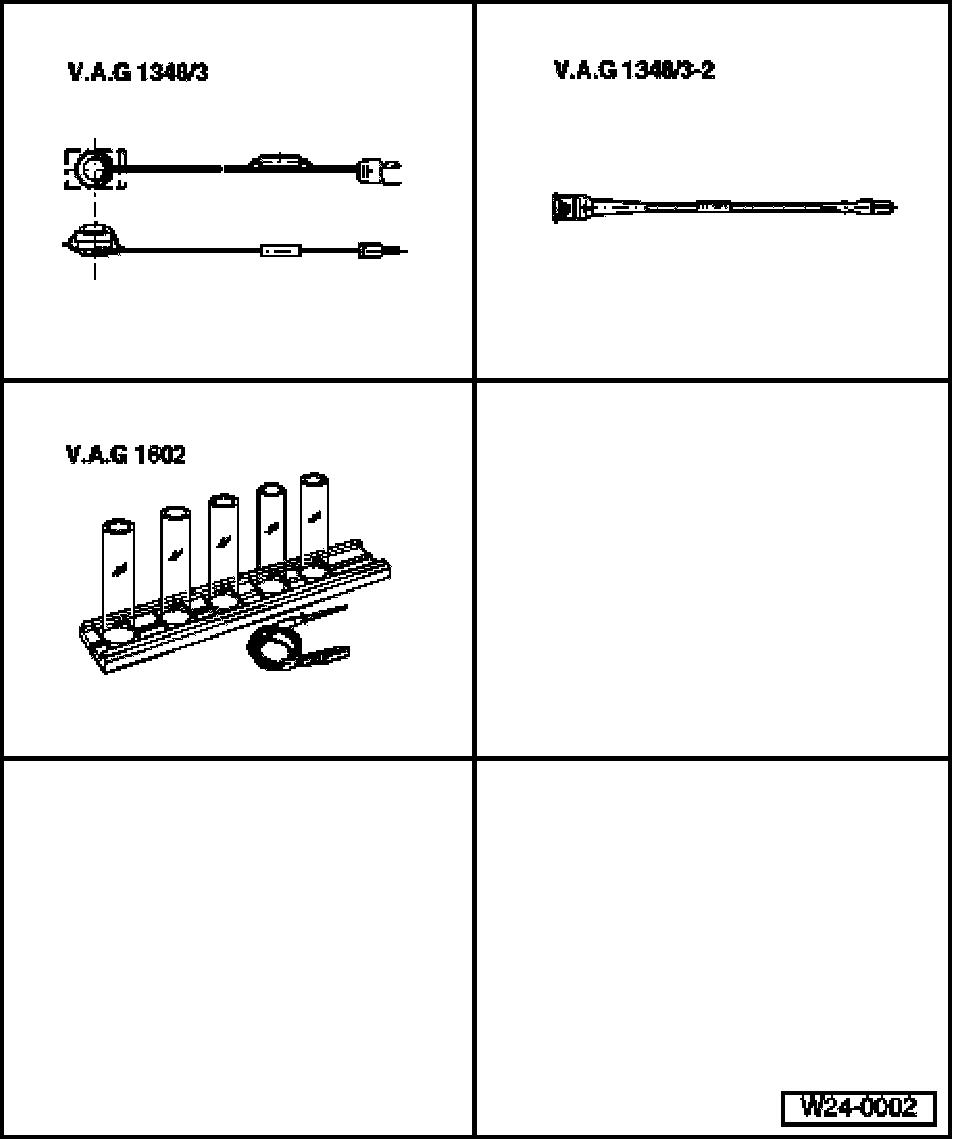
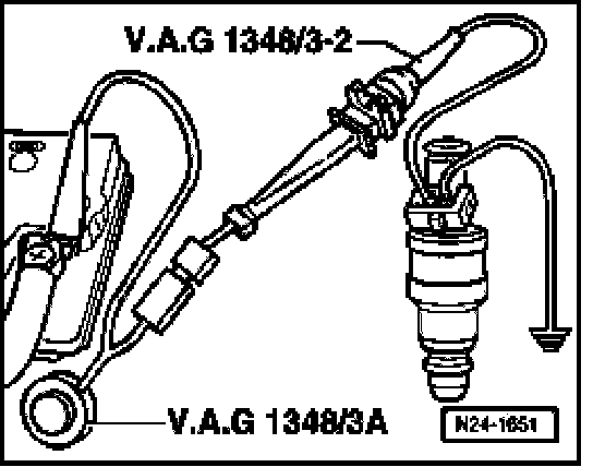
- V.A.G 1348/3A remote control connection with V.A.G 1348/3-2 adapter cable
- V.A.G 1602 tester for quantity of injected fuel
Without illustration:
- V.A.G 1594A Connector test set
Test requirement
- Fuel pressure must be OK, fuel pressure regulator and retaining pressure, checking. Testing and Inspection
WARNING: Fuel system is under pressure! Before opening system, place rags around the connection point. Then release pressure by carefully loosening connection.
Test sequence
- First, remove intake hose between Mass Air Flow (MAF) sensor and intake air scoop.
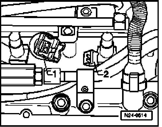
- Pull connectors -1- off connection -2- of all fuel injectors.
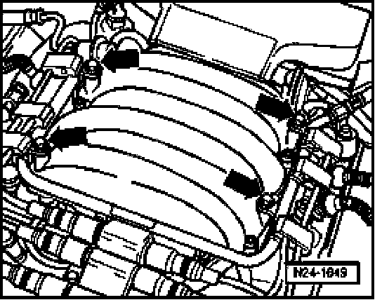
- Unscrew fuel rail from intake manifold (arrows).
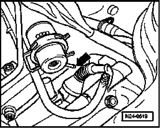
- Disconnect vacuum hose from fuel pressure regulator.
- Lift fuel rail with fuel injectors off intake manifold and support it.
- Connect test box to control module wiring harness, connect test box for wiring test. Test Box, Connecting For Wiring Test
Checking Proper Seal
- Switch ignition on.
Vehicles with engine code AHA
- Bridge sockets 1 + 4 of test box with the respective adapter cables.
Fuel Pump (FP) must run.
Vehicles with engine code ATQ
- Bridge sockets 62 + 65 of test box with the respective adapter cables.
Fuel Pump (FP) must run.
Continuation for all vehicles
- Check proper seal of fuel injectors (visual inspection). With Fuel Pump (FP) running, only 1 to 2 drops per minute should escape from each valve.
- Disconnect connection between test box sockets.
- Switch ignition off.
If fuel loss is greater:
- Replace malfunctioning fuel injector, item 7 .
Note the following when installing the fuel injectors:
- Replace O-rings on all fuel injectors and wet them slightly with clean motor oil.
- Insert fuel injectors into fuel rail perpendicular and in the right position, and secure them with retaining clips.
- Position fuel rail on intake manifold using secured fuel injectors and apply uniform pressure to press it in.
- Erase DTC memory of Engine Control Module (ECM), Diagnostic mode 4: Reset/erase diagnostic data.
- Generate readiness code. Monitors, Trips, Drive Cycles and Readiness Codes
Checking Injection Quantity
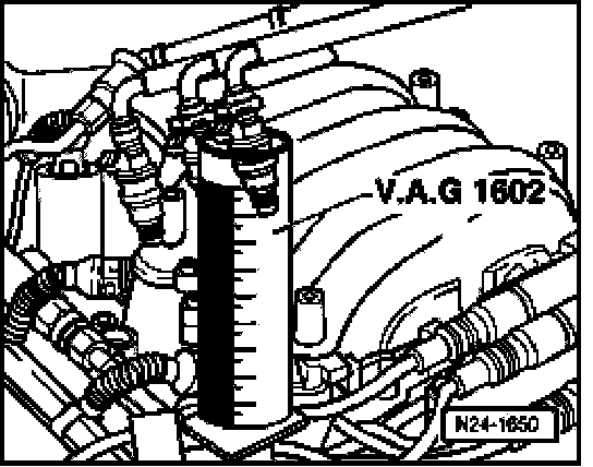
- Insert a fuel injector to be tested into a measuring tube of V.A.G 1602 tester for fuel injection quantity.
- Using respective adapter cables, connect one terminal of fuel injector to be checked to engine Ground (GND).
- Use adapter cable to connect second terminal of fuel injector to V.A.G 1348/3 remote control connection with V.A.G 1348/3-2 adapter cable.
- Connect alligator clip to B+.
- Switch ignition on.
Vehicles with engine code AHA
- Bridge sockets 1 + 4 of test box with the respective adapter cables.
Fuel Pump (FP) must run.
Vehicles with engine code ATQ
- Bridge sockets 62 + 65 of test box with the respective adapter cables.
Fuel Pump (FP) must run.
Continuation for all vehicles
- Operate V.A.G 1348/3 remote control connection for 30 seconds.
- Repeat test on other fuel injectors. Use new graduated measuring glasses for this.
NOTE: Also check spray pattern when checking injection quantity. Spray pattern must be the same for all injectors
- After all fuel injectors have been activated, place graduated measuring glasses on a level surface and compare quantity of injected fuel. Specified value: 90 to 125 ml per injector
- Disconnect connection between test box sockets.
- Switch ignition off.
If the measured value of one or more fuel injectors is below or above the indicated specified value:
- Replace malfunctioning fuel injector, item 7 .
Installation of fuel injectors is the same in reverse order. Note the following:
- Replace O-rings on all fuel injectors and wet them slightly with clean motor oil.
- Insert fuel injectors into fuel rail perpendicular and in the right position, and secure them with retaining clips.
- Position fuel rail on intake manifold using secured fuel injectors and apply uniform pressure to press it in.
- Erase DTC memory of Engine Control Module (ECM), Diagnostic mode 4: Reset/erase diagnostic data.
- Generate readiness code. Monitors, Trips, Drive Cycles and Readiness Codes