Connecting Pipe and Combi-Valves - Assembly Overview
Connecting Pipe And Combi-valves - Assembly Overview

Notes:
- Components marked with an * are checked by the on board diagnostics:
- Checking DTC memory refer to Powertrain Management; Computers and Control Systems
- Components marked with ** are checked by the Output Diagnostic Test Mode (DTM)
- Checking DTM refer to Powertrain Management; Computers and Control Systems
- Secondary Air Injection (AIR) pump relay -J299-, Fig.1
1. - Left combi-valve
- Checking, Testing and Inspection
- Removing and installing, Service and Repair
2. - Gasket
- Always replace
3. - 10 Nm (7 ft. lbs.)
4. - 25 Nm (18 ft. lbs.)
5. - Y piece
6. - Secondary Air Injection (AIR) Solenoid Valve -N112- */**
7. - 6 Nm (53 inch lbs.)
8. - From vacuum reservoir
- Installation location: In left wheel housing
9. - Right combi-valve
- Checking, Testing and Inspection
- Removing and installing, Service and Repair
10. - Gasket
- Always replace
11. - Connection
12. - Gasket
- Always replace
13. - Pressure hose
- Ensure seated tightly
- Press together at front to release
14. - O-ring
- Always replace
15. - Connecting pipe
16. - Connection
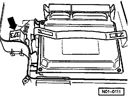
Fig. 1 Secondary Air Injection (AIR) pump relay -J299- (arrow)