Component Tests and General Diagnostics
Voltage Supply For Engine Control Module (ECM), Checking
Recommended special tools and equipment
- V.A.G 1526 multimeter or V.A.G 1715 multimeter
- V.A.G 1594 connector test kit
- Wiring diagram
Test requirements
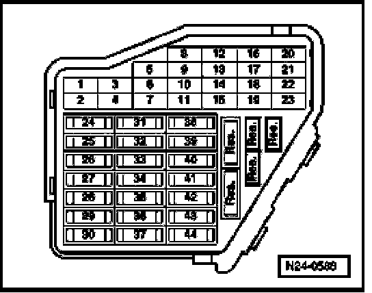
- The respective fuses of Motronic Engine Control Module (ECM) -J220- must be OK
- Fuel Pump (FP) Relay -J17- must be OK, check
- Generator (GEN) must be OK, checking
- Battery voltage must be at least 11.5 volts.
- All electrical consumers such as, lights and rear window defroster must be switched off.
- Parking brake must be engaged or else daylight driving lights will be switched on.
- If vehicle is equipped with an A/C system, it must be switched off.
- Ground (GND) connections between engine and chassis must be OK.
Test sequence
- Connect test box to control module wiring harness, connect test box for wiring test. Test Box, Connecting For Wiring Test
Checking voltage supply at terminal 30
Vehicles with engine code AHA
- Measure voltage supply between sockets 2 + 3 of test box.
Specified value: at least 11.5 V
Vehicles with engine code ATQ
- Measure voltage supply between sockets 1+62 and 2 + 62 of test box.
Specified value: at least 11.5 V
Continuation for all vehicles
If specified value is not obtained:
- Check wire connections to relay carrier and Ground (GND) connection of Engine Control Module (ECM) according to wiring diagram
- Erase DTC memory of Engine Control Module (ECM). Diagnostic mode 4: Reset/erase diagnostic data. Diagnostic Mode 4: Reset/Erase Diagnostic Data
- Generate readiness code. Monitors, Trips, Drive Cycles and Readiness Codes
Checking voltage supply at terminal 15
Vehicles with engine code AHA
- Measure voltage supply between sockets 1 + 2 of test box.
Vehicles with engine code ATQ
- Measure voltage supply between sockets 1+3 and 2 + 3 of test box.
Continuation for all vehicles
- Switch ignition on.
Specified value: at least 11.5 V
If specified value is not obtained:
- Check wire connections to relay carrier and Ground (GND) connection of Engine Control Module (ECM) according to wiring diagram:
- Erase DTC memory of Engine Control Module (ECM). Diagnostic mode 4: Reset/erase diagnostic data. Diagnostic Mode 4: Reset/Erase Diagnostic Data
- Generate readiness code. Monitors, Trips, Drive Cycles and Readiness Codes