Mass Air Flow (MAF) Sensor, Checking
Mass Air Flow (MAF) Sensor -G70-, Checking
NOTE: Use only gold-plated terminals when servicing terminals in harness connector of Mass Air Flow (MAF) sensor.
Recommended special tools and equipment
- V.A.G 1526 multimeter or V.A.G 1715 multimeter
- V.A.G 1594 connector test kit
- Wiring diagram
Test requirements
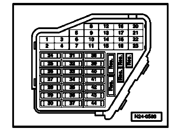
- The respective fuses of Mass Air Flow (MAF) Sensor -G70- must be OK:
- Fuel Pump (FP) Relay -J17- must be OK, check:
- Battery voltage must be at least 11.5 volts.
- All electrical consumers such as, lights and rear window defroster must be switched off.
- Parking brake must be engaged or else daylight driving lights will be switched on.
- If vehicle is equipped with an A/C system, it must be switched off.
- Ground (GND) connections between engine and chassis must be OK.
- Coolant temperature must be at least 80 degrees C. Diagnostic mode 1: Check measured values; PID 5, Coolant temperature. Diagnostic Mode 1: Check Measuring Values
Function test
- Connect diagnostic tester. Diagnostic Tester, Connecting
- Start engine and let run at idle.
- Under address word 33, select "Diagnostic mode 1: Check measured values."
- Select the measuring value "PID 16: Air flow quantity at Mass Air Flow (MAF) sensor".
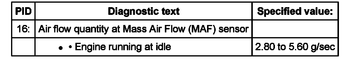
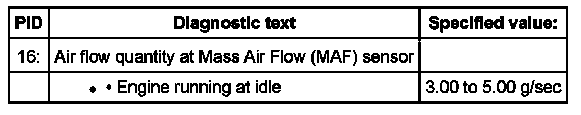
- Check specified value of air flow quantity at Mass Air Flow (MAF) Sensor at idle:
Vehicles with engine code AHA
Vehicles with engine code ATQ
Continuation for all vehicles
- End diagnosis and switch ignition off.
If specified value is obtained, but DTC memory has a DTC concerning Mass Air Flow (MAF) sensor -G70-:
- Check voltage supply of Mass Air Flow (MAF) sensor -G70-.
If specified value is not obtained:
- Check signal and Ground (GND) wires of Mass Air Flow (MAF) sensor.
Voltage supply for Mass Air Flow (MAF) sensor -G70-, checking
Vehicles with engine code AHA
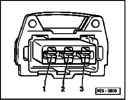
- Disconnect 3-pin connector from Mass Air Flow (MAF) Sensor -G70-.

- Connect multimeter to terminal 3 of connector and engine Ground (GND) for voltage measurement.
- Switch ignition on.
Specified value: at least 11.5 V
- Switch ignition off.
If there is no voltage:
- Check wire between 3-pin connector terminal 3 and relay carrier for open circuit according to wiring diagram.
Wire resistance: max. 1.5 ohms
Vehicles with engine code ATQ
- Disconnect 4-pin connector from Mass Air Flow (MAF) Sensor -G70-.

- Connect multimeter to terminal 3 of connector and engine Ground (GND) for voltage measurement.
- Start engine, and let run at idle.
Specified value: 11.0 to 15.0 V
- Switch ignition off.
If there is no voltage:
- Check wire between 4-pin connector terminal 3 and Fuel Pump (FP) Relay -J17- for open circuit according to wiring diagram.
Wire resistance: max. 1.5 ohms
Continuation for all vehicles
- Check signal and Ground (GND) wires of Mass Air Flow (MAF) sensor.
Checking signal and Ground wires of Mass Air Flow (MAF) Sensor
- Connect test box to control module wiring harness. connect test box for wiring test.
Vehicles with engine code AHA
- Check wires between test box and 4-pin connector for open circuit according to wiring diagram.
Terminal 1 + socket 13
Terminal 2 + socket 12
Wire resistance: max. 1.5 ohms
Vehicles with engine code ATQ
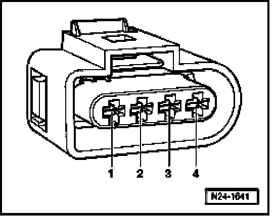
- Check wires between test box and 4-pin connector for open circuit according to wiring diagram.
Terminal 1 + socket 53
Terminal 2 + socket 27
Terminal 4 + socket 29
Wire resistance: max. 1.5 ohms
Continuation for all vehicles
- Also check wires for short circuit to each other, to vehicle Ground (GND) and to B+.
Specified value: Infinite ohms
If no DTCs are found in wires:
- Replace Mass Air Flow (MAF) Sensor -G70-
- Erase DTC memory of Engine Control Module (ECM). Diagnostic mode 4: Reset/erase diagnostic data. Diagnostic Mode 4: Reset/Erase Diagnostic Data
- Generate readiness code. Monitors, Trips, Drive Cycles and Readiness Codes