Fuel Supply
Fuel Pump, Checking
Special tools, testers and auxiliary items required
• Torque wrench (VAG 1332)
• Connector test set (VAG 1594C)
• Voltage tester (VAG 1527B)
• Measuring container
• Wrench (T10202)
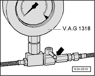
• Pressure gauge (VAG 1318)
• Adapter (VAG 1318/7)
• Pressure gauge adapter (VAG 1318/10)
• Hose (VAG 1318/13)
• Remote control connection (VAG 1348/3A)
• Multi meter (VAG 1715)
• Wiring diagram
--> [ Function and Voltage Supply, Checking ]
--> [ Fuel Pressure, Checking ]
--> [ Residual Pressure, Checking ]
--> [ Delivery Quantity, Checking ]
--> [ Current Draw, Checking ]
Function and Voltage Supply, Checking
Test Conditions
• Battery voltage at least 11.5 V
• Fuse for Fuel Pump (FP) is OK.
• FP control module (J538) is OK.
• Low fuel pressure sensor (G410) is OK.
Test Sequence
- Read safety precautions before beginning work.
- Observe the rules for cleanliness.
- Switch ignition on. Fuel pump must run audibly for approximately 2 seconds.
- Switch off ignition.
If FP Does Not Start Up
- Fold rear seat bench forward. On vehicles from 12.06, rear seat bench must be removed.
- Cut open the carpet on the right side from point - A - to point - B - in the precut area - arrow -.

- Remove the nuts - 1 - for the right side fuel delivery unit cover. If necessary, remove backrest support - 2 - or mounting bracket.

- Disconnect connector from FP control module (J538) - 5 -.

- Switch ignition on.
- Check voltage supply between connector terminals - 3 - and - 4 - using voltage tester (VAG 1527B). Light Emitting Diode (LED) must light up.

- Switch off ignition.
LED Does Not Light Up
- Locate and repair open circuit in wiring using wiring diagram.
LED Lights Up (Voltage Supply OK)
CAUTION!
Fuel supply line is under pressure! Wear protective goggles and protective clothing to prevent injuries and contact with skin. Before separating hose connection, wrap a cloth around the connection. Then release pressure by carefully separating the connection.
- Remove fuel supply line - 1 -, auxiliary heater fuel line - 2 -, fuel pump connector - 3 - and vent line - 4 -.
• Press in securing ring to disengage the fuel line.
- Open locking ring using wrench (T10202).

- Check whether electrical wires between flange and FP are connected.
If no open circuits are found:
- FP faulty, replace fuel delivery unit.
Fuel Pressure, Checking
- Read safety precautions before beginning work.
- Observe the rules for cleanliness.
CAUTION!
Fuel supply line is under pressure! Wear protective goggles and protective clothing to prevent injuries and contact with skin. Before loosening the hose connection, wrap a cloth around the connection. Then release pressure by carefully loosening the union nut.
- Place a cloth around the connection and loosen the union nut - arrow - in order to reduce fuel pressure.
- Then tighten the threaded connection again.

- Connect the pressure tester (VAG 1318) with adapter (VAG 1318/7), adapter (VAG 1318/10) and adapter (VAG 1318/13) as shown.
- Make sure hose clamps are seated securely.

- Open shut off valve of pressure gauge set. The lever points in the direction of flow.
- Fold rear seat bench forward. On vehicles from 12.06, rear seat bench must be removed.
- Cut open the carpet on the right side from point - A - to point - B - in the precut area - arrow -.
- Remove the nuts - 1 - for the right side fuel delivery unit cover. If necessary, remove backrest support - 2 - or mounting bracket.
- Disconnect connector from Fuel Pump (FP) control module (J538) - 5 -.
- Disconnect harness connector - 3 - from flange of fuel delivery unit.
- Connect the remote control (VAG 1348/3A) with adapter cables from connector test kit (VAG 1594C) to terminal - 1 (+) - of FP and to terminal - 3 (+) - of harness connector of FP control module (J538).

- Connect terminals - 4 (-) - of harness connector and - 4 (-) - of FP using an adapter cable from connector test kit (VAG 1594C).
- Switch ignition on.
- Operate the remote control (VAG 1348/3A) and observe display of pressure tester (VAG 1318) while doing this.
Fuel pressure must increase up to a maximum pressure of 6 bar.
• When releasing control button of the remote control (VAG 1348/3A), fuel pressure decreases to approximately 5.6 bar.
If fuel pressure is OK, check retaining pressure, refer to --> [ Residual Pressure, Checking ].
If the Specification is Exceeded
- Pressure relief valve in the sensor flange is faulty, replace sensor flange --> [ (Item 15) Flange ] .
If the Specification is Not Obtained
- Check the fuel lines for possible restrictions (kinks) or blockages.
- Check all fuel lines in fuel tank for leaks.
- Check fuel filter for leaks.
If no malfunction can be found:
- Replace sensor flange with pressure relief valve --> [ (Item 15) Flange ] .
- Repeat the test.
If fuel pressure is not obtained again:
- FP faulty, replace fuel delivery unit.
Residual Pressure, Checking
Test Conditions
• The pressure gauge (VAG 1318) remains connected. Refer to --> [ Fuel Pressure, Checking ].
• Fuel pressure of approximately 5.6 bar is displayed on pressure tester (VAG 1318), checking. Refer to --> [ Fuel Pressure, Checking ].
• Remote control (VAG 1348/3A) is connected.
Test Sequence
- Watch pressure drop on gauge. After 10 minutes the pressure must not drop below a 4.0 bar decrease.
If the pressure drops below 4.0 bar:
- Operate the remote control (VAG 1348/3A) and observe display of pressure tester (VAG 1318) while doing this.
Fuel pressure must increase up to a maximum pressure of 6 bar.
- Release control button for the remote control (VAG 1348/3A) and immediately close the shut off valve on the pressure tester. Lever then points perpendicular to flow direction - arrow -.
• When releasing control button for the remote control (VAG 1348/3A), fuel pressure decreases to approximately 5.6 bar.
If the Pressure Drops Below 4.0 Bar Again
(Leak on fuel tank side)
- Check connections to fuel tank for leaks.
If no malfunction can be found:
- Check fuel filter for leaks.
- Check fuel line to sensor flange --> [ (Item 15) Flange ] , for leaks.
- Check all additional fuel lines in fuel tank for leaks.
If no malfunctions are found on fuel line:
- Pressure relief valve in fuel delivery unit flange faulty.
- Replace sensor flange with pressure relief valve --> [ (Item 15) Flange ] .
Delivery Quantity, Checking
- Release the high pressure in the fuel system.
CAUTION!
Fuel supply line is under pressure! Wear protective goggles and protective clothing to prevent injuries and contact with skin. Before loosening hose connection, wrap a cloth around the connection. Then release pressure by carefully loosening the union nut.
Test Sequence
- Read safety precautions before beginning work.
- Observe the rules for cleanliness.
• A second technician is needed for the following task.
- Connect the pressure gauge (VAG 1318) with adapter (VAG 1318/7), adapter (VAG 1318/10) and adapter (VAG 1318/13) as shown.
- However, do not connect the end of hose (VAG 1318/13) to the fuel rail connector.
- Hold the end of hose (VAG 1318/13) in a measuring container.
- Open the shut off valve for the pressure gauge (VAG 1318). The lever points in the direction of flow.
- Switch ignition on.
- Operate the remote control (VAG 1348/3A). Slowly close the shut off tap, until pressure gauge shows 4 bar fuel pressure. From this point on do not move position of the shut off tap.
- Do not operate the remote control (VAG 1348/3A) any more.
- Empty measuring container.
- Now operate remote control (VAG 1348/3A) for 15 seconds.
- Compare quantity of fuel delivered with minimum delivery rate in diagram (cm3/15s).

• Voltage at fuel pump with engine stopped and pump running is approximately 2 volts less than battery voltage.
If the minimum delivery rate is not attained:
- Check the fuel lines for possible restrictions (kinks) or blockages.
If lines are OK:
- Replace fuel filter.
- Repeat the test.
If specified value is again not obtained:
- Fuel Pump (FP) faulty, replace fuel delivery unit.
If the delivery rate has been attained but nevertheless you suspect a fuel supply system malfunction (e.g. intermittent failure of fuel supply system):
- Check FP current draw. Refer to --> [ Current Draw, Checking ].
Current Draw, Checking
- Check the current draw of the fuel pump as follows:
- Reconnect all disconnected fuel lines.
- Connect the multi meter (VAG 1715) with electrical current probe to the wire of the 4 pin connector terminal - 1 - - arrow - from wiring harness to Fuel Pump (FP) unit, right.
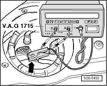
- Start the engine and run at idle speed.
- Measure current draw of fuel pump. Specified value: max. 11 amps.
If the current draw is exceeded:
- FP faulty, replace fuel delivery unit.
• If malfunction in fuel system is sporadic, test can also be performed during a road test, but a second person is required.