ABS Mark 70, ABS and ASR
Control Module and Hydraulic Unit
Special tools, testers and auxiliary items required
• Torque wrench (VAG 1331)
• Torque wrench (VAG 1410)
• Brake pedal actuator (VAG 1869/2)
Sealing Plug Repair Set, Part No. 1H0 698 311 A

1 Transport protection for valve domes (foam)
2 Sealing plug M10 threads
3 Sealing plug M12 threads
After separating the control module from the hydraulic unit, always install transport protection - 1 - on the hydraulic unit for the valve domes.
Warranties will not be granted for hydraulic units without transport protection.
Component Location
The control module is bolted to the hydraulic unit and is located on the right side in the engine compartment.
Removing
CAUTION!
Do not bend the brake lines near the hydraulic unit.
- Read and note the present control module coding.
- Note or request the radio code on vehicles with a coded radio, if necessary.
- Disconnect the battery.
- Remove the engine cover.
- Release the control module connector in - direction of arrow 1 - and pull off in - direction of arrow 2 -.

- Install the brake pedal actuator (VAG 1869/2).
- Attach the bleeder hose from the bleeder bottles to left front and left rear brake caliper bleeder valves and open the bleeder valves.
- Press the brake pedal at least 60 mm using the brake pedal actuator (VAG 1869/2).
- Close the left front and left rear bleeder valves.
- Do not remove the brake pedal actuator (VAG 1869/2 ).
- Place sufficient lint free cloths under the control module and hydraulic unit.
Make sure that brake fluid does not come in contact with the electrical terminals.
- First, mark both brake lines - A and B - from the master cylinder and remove them from the hydraulic unit.

- Plug the brake lines and threaded holes immediately with sealing plugs from the repair kit part no. 1H0 698 311 A.
- Mark the brake lines - 1 to 4 - (from the brake calipers) , and remove them from the hydraulic unit.
- Plug the brake lines and threaded holes immediately with sealing plugs from the repair kit part no. 1H0 698 311 A.
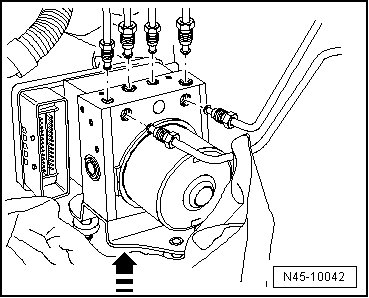
- Pull the hydraulic unit with control module upward off of the bracket.
Removing Control Module from Hydraulic Unit
- Set the hydraulic unit with control module upward on to a clean, level surface.
- Remove the inner Torx bolts - arrows -.

- Pull the control module off from the hydraulic unit - arrow - without tilting.

- Carefully pull off all sealing rings from the valve domes of the hydraulic unit.
CAUTION!
• On a disconnected control module, circuit board is laid open.
• No moisture or particles of dirt must penetrate in interior of control module.
• The hydraulic pump must not be separated from the hydraulic unit.
• Avoid buildup of static electricity!
- Cover control module magnetic coils with a lint free cloth.
After separating the control module and hydraulic unit, use transport protection for the valve body.
Installing
Installing the New Control Module
CAUTION!
Excessive shaking (e.g. dropping, impact) may destroy the control module. Control module must then no longer be used.
• Surface must be cleaned before assembling.
- Slide all the sealing rings - A - on slightly over the valve domes.

- Place the control module without tilting it onto the hydraulic unit.
The sealing rings are then brought into their end position.
- Bolt the hydraulic unit and control module together with the new inner Torx bolts supplied.
• A new control module may be installed a max. of two times to a used hydraulic unit, to ensure that the elastic gasket seals sufficiently.
• A control module which was once in driving operation must not be installed a second time.
Installing Control Module and Hydraulic Unit
• Do not remove sealing plugs from the new hydraulic unit until the corresponding brake line is about to be installed.
• If the sealing plugs are removed too early, brake fluid can leak out. If this occurs, unit may not be sufficiently filled or adequately bled.
• When installing, make sure that rubber insulators are not pressed out of the bracket.
- Installation is performed in the reverse order of removal.
- Remove the brake pedal actuator (V.A.G 1869/2 ).
- Bleed the brake system. Refer to => [ Brake System Bleeding General Information ] Brake System Bleeding General Information.
- Enter radio code.
- Code the Anti-lock Brake System (ABS) control module with the in "Guided Fault Finding".
