Assembly
1. On vehicles without limited slip [1][2]differential, install thrust washers and large differential gears into case using suitable nut, bolt and washers to retain them. Tighten nuts to compress thrust washers. Install small differential gears and thrust washers into housing as an assembly and remove nut, bolt and washers. Install differential gear shaft and lock pin.
2. On vehicles without limited slip [1][2]differential, install ring gear onto carrier assembly. Using new bolts, torque standard head bolts to 50-58 ft. lbs. (70-80 Nm), torque flanged head bolts to 65-80 ft. lbs. (90-110 Nm).
3. On vehicles with limited slip [1][2]differential, install ring gear onto carrier assembly. Coat new bolt threads with a suitable sealing compound and install bolts. Torque standard head bolts to 50-58 ft. lbs. (70-80 Nm), torque flanged head bolts to 65-80 ft. lbs. (90-110 Nm). Install shafts, gears and discs into differential housing. Torque bolts to 44-55 ft. lbs. (60-75 Nm).
Fig. 4 Adjusting ring & tool for pinion location:
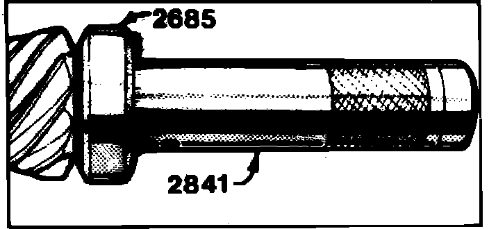
4. On type 1030 axle, install adjusting ring 2685 and wrench 2841 or 5157 onto pinion, Fig. 4. On type 1031 axle, install adjusting ring 2840 and wrench 2841 or 5157 onto pinion.
5. Install pinion into housing. Ensure screw head on adjusting ring faces the larger part of the differential carrier. Ensure adjusting ring pin is in the differential carrier recess.
6. Check pinion depth with tool Nos. 2284 and 2393 and a dial indicator as follows:
Fig. 5 Rear Axle Measuring Tools:
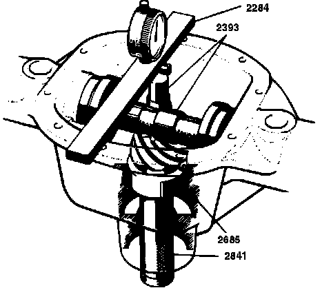
a. Place gauge plug on machined surface of pinion, install tool No. 2393 in housing in place of carrier and place dial indicator in tool No. 2284, then place tool across machined surface of housing, Fig. 5.
Fig. 6 Checking Pinion Depth:
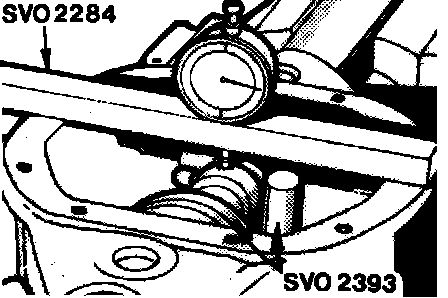
Fig. 7 Measuring Pinion Location:
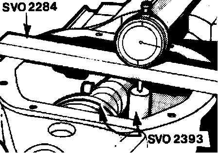
b. Place dial indicator on tool, Fig. 6, and zero indicator. Move indicator retainer so that indicator comes in contact with gauge plug. The machined surface of the pinion is marked with a nominal dimension. The reading taken in Fig. 7 should equal the nominal dimension as marked on pinion.
c. If pinion, for example, is marked 33, gauge plug should be .33 mm (.013 in.) under adjusting fixture. Nominal dimensions on pinion are in metric measurements on all late units, however, some early units are marked in thousandths of an inch. Metric units have no plus or minus sign. Inch units are marked plus or minus. On inch units, if pinion is marked (-) minus, gauge plug should be higher than adjusting fixture. If marked (+) plus, gauge plug should be lower. Pinion height is adjusted to proper value by turning tool No. 2841 until height is correct. Lock the lock screw on the adjusting ring. Remove adjusting ring from pinion.
Fig. 8 Measuring Adjusting Ring & Bearing:
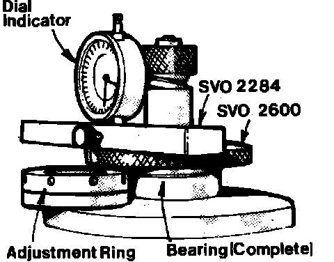
7. Place the complete rear pinion bearing with the outer ring in fixture 2600, Fig. 8. Turn bearing back and forth to seat rollers. Tighten knurled nut down to hold bearing fully seated. Place adjusting ring in fixture, Fig. 8.
8. Use dial indicator and tool No. 2284 to check difference in height between adjusting ring and bearing. This is the correct thickness for the pinion bearing shims. Measure out the correct shim thickness with a micrometer. It is almost impossible to obtain a shim with exactly the correct thickness. Shims must not be more than .02 mm (.0082 in.) thicker than the measured value, but can be up to .05 mm (.002 in.) thinner.
9. Press rear pinion bearing onto pinion.
10. The measured shims obtained are installed in the housing under the bearing race for the rear pinion bearing. Do not install washer that was under bearing cup originally. The measured shims will provide proper pinion depth.
Fig. 9 Installing Bearing Races (typical):
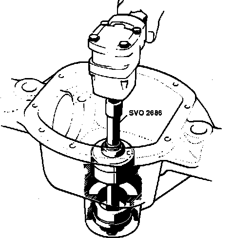
11. Install both bearing races with tool No. 2686 on type 1030 axles or 2842 on type 1031 axles, Fig. 9.
12. Insert pinion into housing, then install three .75 mm (.030 in.) shims and front pinion bearing. Using tool Nos. 1845 and 2404, pull in pinion.
13. Replace tool No. 1845 with washer and nut. Torque nut to 250 Nm (185 ft. lbs.).
14. Using the dial indicator and tool No. 2284, check pinion endplay.
15. Remove pinion. Reduce thickness of front shim pack according to dial indicator reading plus .0035 inch (.09 mm) for new bearings. On used bearings, reduce thickness of front shim pack according to dial indicator reading plus .0028 inch (.07 mm).
16. Using the above shim pack, install pinion as outlined in Step 13. Check the torque necessary to rotate the pinion. For used bearings, 13-22 inch lbs. should rotate the pinion. For new bearings, 22-31 inch lbs. Higher torque on new units may occur. Higher torque is not a cause for concern, but if torque does not meet minimum values, reduce the front bearing shim pack to obtain the correct torque.
17. Lubricate the inside of adjusting rings 2595 and install them on the differential carrier in place of the carrier bearings. The ring with the black oxidized ring should be placed on the ring gear side. Install the differential assembly in the housing.
18. Turn the adjusting rings to adjust the ring gear position to obtain a gear backlash of .15 mm (.006 in.). Tighten the lock screws. Previously, the gear contact pattern could be used to determine correct installation of the gears. This is no longer possible because of altered manufacturing and test procedures. The pinion should always be installed according to its number marking regardless of the contact pattern.
19. Install each carrier bearing assembly in tool No. 2600. Follow procedure outlined to determine the proper shim thickness for each carrier bearing. Place the right bearing in the tool and measure the adjusting ring that was on the right side of the carrier. When each shim pack has been determined, add .07 mm (.003 in.) to each side for preload. Install shims on carrier and press on the carrier bearings.
20. Install tool No. 2394 on the housing. Expand the tool until the tool pins are tight in the holes in the housing, then turn the tensioning screw an additional 3 to 3-1/2 turns. Install the [1][2]differential and bearing rings.
21. Remove tool No. 2394.
22. Install the caps according to their markings and torque to 50-70 Nm (36-50 ft. lbs.).
23. Remove tool No. 2404 from pinion. Install oil seal.
24. Press on the flange with tool No. 1845 or 5156.
25. Install washer and nut. Torque nut to 185 ft. lbs. (250 Nm).
26. Install differential cover with a new gasket.
27. Install axle shafts.