Assembling M45

1. Connect 1-2 and 3-4 synchro hubs. Position hub in sleeve so that hub slots align chamfered teeth in sleeve. Insert dogs (three) and lock them with springs.
NOTE: With curved lock ring, align springs to let free ends press against synchro ring.

2. Install rear cover seal. Use drift P/N 5064.

3. Install bell housing seal. Use drift P/N 2867 and standard handle P/N 1801.

4. Install seal for selector rail. Use drift P/N 5065.

5. Position rubber ring in joint.
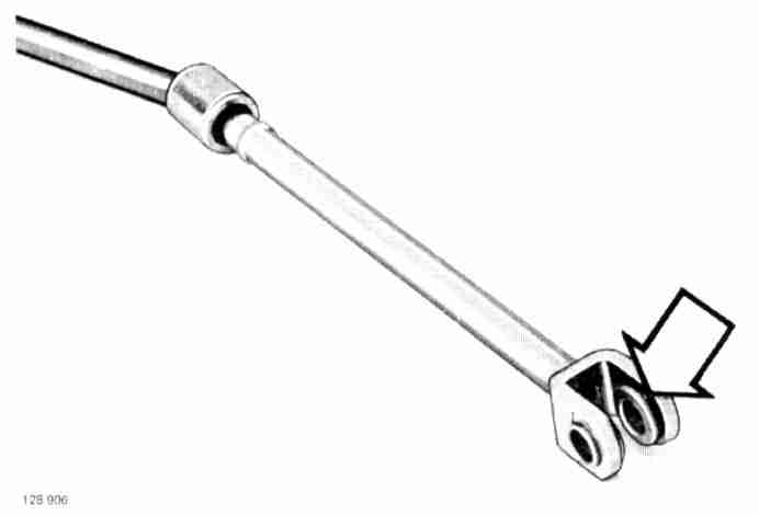
6. Connect gear selector rail and gearshift rod. Selector rail grooves UP.
7. Install sleeve on joint.
8. Install bushings on gearshift rod. Use grease to retain rubber ring on one side.

9. Install:
- 3rd gear and synchro ring.
- 3-4 synchro hubs on main shaft.
- Lock ring.
Use adapter P/N 2852 when pressing on gear and hub.

10. Install:
- 2nd gear and synchro hub.
- 1-2 synchro hub on main shaft.
- Lock ring.
Use adapter P/N 2852 when pressing on gear and hub.

11. Install 1st gear and synchro ring on main shaft.

12. Install two intermediate shaft bearings. Use drift P/N 2986 to press on bearings.
NOTE: Intermediate shaft small end bearing is different for diesel applications. Use correct type bearing.
2412 Drift:

13. Install bearing on input shaft. Use drift P/N 2412 to press on bearing.

14. Install lock ring on input shaft.
NOTE: DO NOT install spacer ring on bearing at this time. It will be installed later on.
CAUTION: Special instructions for transmission with aluminum housing. Prior to further assembly, intermediate shaft pretension should be determined. Follow operations 15-24.

15. Position intermediate shaft in housing.
16. Position outer races for intermediate shaft bearings. Use drift P/N 5180, large outer diameter toward race.

17. Install bell housing with gasket. Torque bolts to 35-50 Nm (25-35 ft lb).

18. Turn transmission to vertical position.
19. Eliminate clearance in intermediate shaft bearings. Use drift P/N 5180, small diameter toward rear race. Hold drift rigidly and knock in race with light taps. Repeat while rotating shaft, until all clearance is gone and shaft runs somewhat sluggish.

20. Measure distance between intermediate shaft bearing outer race and rear surface of housing. Use depth gauge and note reading.


21. Determine thickness of shims for intermediate shaft. Shaft pre-tension should be 0.03-0.08 mm. Gasket thickness 0.25 mm (metric only).
22. Remove bell housing and gasket.

23. Remove outer races for intermediate shaft bearings. Carefully knock intermediate shaft in until puller P/N 5177 can grip races.
24. Lift out intermediate shaft.
CAUTION: End of special instructions for transmissions with aluminum housing. Continue assembly, using same operations as for transmission with cast iron housing.
Exception:
^ Outer races for intermediate shaft bearings are installed as described above.
^ Shim thickness is determined.
25. Install reverse gear shifter. Install lock ring.

26. Install reverse gear and shaft.

27. Check and adjust reverse gear shaft position. Shaft end should be minimum 0.05 mm (0.002 in) under housing face.

28. CAUTION: Adjust clearance between reverse gear and shift fork. Correct clearance is 0.1-1.0 mm (0.004-0.04 in). Adjust by knocking shift fork pivot pin axially with a punch.

29. Position intermediate shaft in housing. Position on bottom of housing.
30. Position main shaft in housing.

31. Position thrust washer and bearing on main shaft. Bearing should be fitted with positioning ring.

32. Press main shaft bearing into position. Use press tool P/N 2831. Press reverse gear toward transmission center. Check that no gears coincide and become damaged.

33. Use spacer for tool if bearing does not align correctly. Spacer should be positioned between tool spindle and housing front end. Bearing positioning ring should be flush with housing face when bearing is correctly positioned.

34. Grease and install input shaft roller bearing.

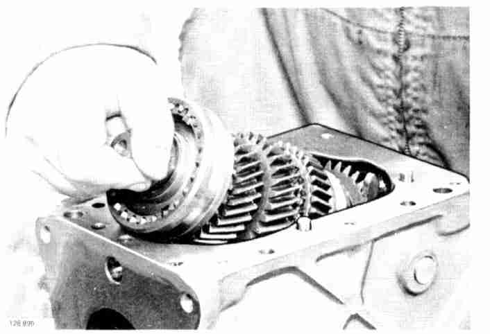
35. Position 4th gear synchro ring in synchro hub.

36. Attach input shaft to main shaft. Push shaft in all the way.
37. Lift up intermediate shaft. Position shaft so bearings are correctly positioned in housing.

38. Pull out input shaft so that spacer ring can be positioned on bearing. Then push in shaft again. Spacer ring should lie against housing
39. Cast iron housing: Install intermediate shaft outer bearing races.

40. Aluminum housing: Install intermediate shaft outer bearing races. Use drift P/N 5180, large outer diameter toward bearing races.

41. Measure distance between front end of input shaft bearing and housing front surface. Use depth gauge. Note reading (metric).

42. Measure distance between bell housing surface and bearing seat bottom. Use depth gauge. Note reading (metric).

43. Determine shim thickness for input shaft. Axial clearance permitted: 0.01-0.20 mm.
NOTE: Gasket thickness 0.25 mm must also be considered. Use metric measurements only.
44. Attach bell housing. Use grease on gasket and shim to keep in place. Torque to 35-5O Nm (25-35 ft lb).
45. Aluminum housing: Install clutch fork. Including spacer.
46. Aluminum housing: Install throw-out bearing.

47. Aluminum housing: Turn transmission to vertical position. Make sure intermediate shaft bearings have no clearance. Use drift P/N 5180 with small diameter toward rear bearing race. Hold tool rigidly and knock on race with light knocks. Repeat while rotating shaft until all clearance is gone and shaft runs somewhat sluggish.

48. Cast iron housing: Turn transmission vertical position. Measure distance between intermediate shaft bearing outer race and rear surface of housing. Race should butt rollers. Use depth gauge. Note reading (metric).

49. Determine thickness of shims for intermediate shaft. Axial clearance permitted: 0.025-0.10 mm. Gasket thickness: 0.25 mm. Metric only.

50. Measure distance between front of main shaft bearing and housing rear surface. Use depth gauge. Note reading (metric).

51. Measure distance between rear cover surface and bearing seat bottom. Use depth gauge. Note reading (metric).

52. Determine shim thickness for main shaft. Axial clearance permitted: 0.01-0.20 mm. Gasket thickness: 0.25 mm.

53. Install speedometer drive gear, gasket and shim pack for intermediate shaft. Speedometer gear flange toward bearing. Shim pack determined in steps above:
- 15-24 for transmissions with aluminum housing.
- 48-49 for transmissions with cast iron housing.

54. Position shim for main shaft in rear cover. Apply grease to shim to keep it in place.

55. Install rear cover. Install two outer (lower) bolts finger tight. Install seal in rear cover using drift P/N 5064.

56. Install drive flange. Use wrench P/N 5149 to hold flange. Torque nut to 90-110 Nm (65-80 ft lb).

57. Install speedometer driven gear with O-ring.

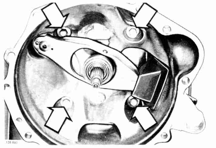
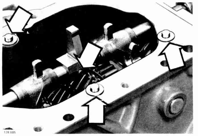
58. Install gearshift carrier. Note sequence: bolt - washer - spacer - washer. Torque bolts to 35-50 Nm (25-35 ft lb).
59. Install two inner (lower) bolts for rear cover. Torque four lower bolts to 35-50 Nm (25-35 ft lb).
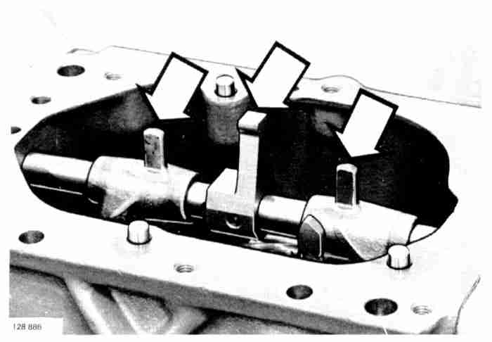
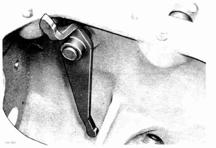
60. Install shift forks. Make sure lugs position correctly.
61. Install shifter and gear selector rail. Shifter boss forward.
62. Install:
- Lock pin for shifter.
- Glide washers for selector plate assembly.

63. Install selector plate assembly and return spring.

64. Check operation. Install gearshift lever without lock screw and lock ring. Hold selector plate assembly with palm. Check gearshift operation and correct as necessary. Remove gearshift lever.

65. Install:
- Detent ball and spring.
- New top cover gasket.

66. Install:
- Top cover. Torque bolts to 15-25 Nm (11-18 ft lb).
- Back-up light switch.
- Sound deadening material on gearshift carrier.

67. Fill oil. Lower transmission rear end. Fill 0.75 liter (0.8 qt) of Automatic Transmission Fluid type F or G.
68. Install level plug.