Assembling M46

Assembling Main Shaft
1. Assemble both synchronizers. Place hub in operating sleeve. 3rd-4th gear synchronizer: Three recesses in hub should align with the three bevelled teeth in operating sleeve.

2. Install sliding keys (1) and springs (2).
- Lock sliding keys ("dogs") with springs. Hook both springs to the same sliding key.
- Install one spring counter-clockwise. Turn synchronizer over and install second spring, also counter-clockwise.
- If spring is bent, free end must point away from hub.

3. Oil main shaft. Install 3rd gear wheel and synchronizer.
- Press on 3 rd-4th gear synchronizer hub.
NOTE: On some transmissions, the gear wheel has a needle bearing. Make sure that it is fitted.
- Make sure synchronizer ring is facing correct way. Turn wear surface on synchronizer hub UP.
- Use support 2852.

4. Invert shaft. Oil shaft. Install 2nd gear wheel and synchronizer. Press on 1st-2nd gear synchronizer hub. Make sure synchronizer ring is fitted correctly. Use support 2852.
5. Install lock rings for both synchronizers.

6. Transmission without damper:
Install synchronizer ring and gear wheel for 1st gear.

7. Transmission with damper: Install thrust washer (1), if applicable, synchronizer ring (2) and gear wheel (3) for 1st gear.
8. Assemble damper. Oil parts. Position springs in brake ring and twist washer into brake ring.
9. Press damper (4) on main shaft. Use a file to remove sharp edges. Use tube P/N 5090 when pressing on damper.

10. Press both bearings on main shaft. Use drift 2986.
NOTE: Two types of rear bearings. Check transmission serial number to see that correct bearing is used.

11. Press bearing on input shaft. Use standard handle P/N 1801 and support P/N 2853.
12. Install lock ring on input shaft.
NOTE: For transmissions with cast iron housing: proceed to operation 22. Operations 13-21 only apply to transmissions with aluminium housing.
Determining Thickness Of Countershaft Shims
The countershaft should have a preload of +0.03 to -0.05 mm (end float 0.05 to a preload 0.03 mm) (+0.0012 to -0.0020 in). If the transmission assembly is equipped with a 1st gear brake, the end float should be 0.0 to +0.05 mm (0.0 to +0.0020 in). If countershaft, countershaft bearing or rear end bearing was replaced, shim thickness must be determined.
NOTE: Apply assembly paste to aluminium surfaces prior to installing bearings and shafts. Part Number 1 161 006-0 Aerosol, 1 161 078-9 Can.
5180 Drift:

13. Install countershaft in housing.
14. Install front bearing race for countershaft Use drift P/N 5180 large end facing race. Let race protrude approx. 1 mm (0.04 in). It will take up correct position when installing clutch cover.

15. Install clutch housing and gasket. Torque to 35-50 Nm (25-35 ft lb).
16. Turn transmission so that rear end faces UP.
17. Install rear bearing race for countershaft. Use drift P/N 5180 small diameter facing rear bearing race. Make sure bearing has no play. Rotate shaft and tap until there is no play (shaft has light resistance).

18. Measure distance between outer bearing race for countershaft and housing end face including gasket.
- Position gasket on end face.
- Use depth micrometer and note distance.


19. Calculate thickness of shim for countershaft.
20. Remove clutch cover and gasket.
21. Remove countershaft.
NOTE:Continue assembling transmission as described for transmission with cast iron housing. The only difference is installing countershaft and determining shim thickness, as described above.

Installing Shafts In Transmission Housing
22. Install gear selector for reverse gear. Install lock ring for shift fork.
23. Install reverse gear wheel and shaft.

24. Check/adjust position of reverse gear shaft. Shaft end should be flush with housing or max. 0.05 mm (0.002 in) inside housing face.
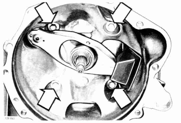
25. Check/adjust clearance between reverse gear wheel and shift fork.
- Adjust by tapping shift fork bearing stud, using a drift. See illustration.
- Correct clearance: 0.1-1.0 mm (0.004-0.040 in).

26. Place countershaft in bottom of housing.
27. Place main shaft in housing. First turn housing.

Installing Main Shaft Rear Bearing
28. Install thrust washer (only transmissions with-out damper) and bearing with lock ring on main shaft. Countershaft should be positioned in bearings.

29. Press main shaft bearing into position. Use press tool P/N 5306.
CAUTION: Make sure gear teeth do not clash and become damaged when pressing on bearing.
30. Make sure lock ring on bearing contacts housing. If required, tap press tool with a mallet until bearing positions correctly.

Installing Input Shaft
31. Position 4th gear synchronizer ring in synchronizer hub.
32. Grease and install roller bearing in input shaft.

33. Install input shaft, lift countershaft.
- Tap bearing outer race with a mallet if bearing is stiff.
- Place countershaft bearings in position before input shaft.

34. Install outer races for countershaft. Transmission with aluminium housing, use drift P/N 5180.
Front bearing: large end of drift.
Rear bearing: small end of drift.

35. Grease and install seal in bell housing.
- First check that tube bottoms.
- Use drift P/N 2687 and standard handle P/N 1801.
Determining Thickness For Shim On Input Shaft
Input shaft should have an end clearance of 0.01-0.20 mm (0.0004-0.0080 in). If bearing on input shaft or bell housing was replaced, shim thickness must be determined.

36. Measure distance between outer face of in put shaft bearing and front face of transmission.
- Make sure lock ring on bearing abuts housing.
- Use depth micrometer and note reading.
37. Position gasket on clutch housing.

38. Measure distance between outside of gasket and bottom of bearing seat. Note reading.

39. Calculate shim thickness for input shaft.

Installing Clutch Housing ("bell Housing")
40. Grease transmission gasket face and install gasket.
41. Position shim in clutch housing. Apply grease to hold shim in position.
42. Install clutch housing. Torque to 35-50 Nm (25-35 ft lb)

43. Install clutch fork, spacer washer and clutch release bearing.
- Prior to installing, grease bearing sliding surface and ball joint.
- Sparingly apply grease to splines. (Do not forget washer under ball joint.)
NOTE: Transmissions with aluminium housing: proceed to operation 46. Operation 44-45 only apply to transmissions with cast iron housings.
Determining Thickness For Shim On Countershaft
End float should be 0.025-0.10 mm (0.001-0.004 in). If the countershaft, any of its bearings, or the rear case/intermediate housing have been replaced the shim thickness should be determined.

44. Make sure bearing races are correctly positioned. Depress races while turning main shaft a couple of turns until bearing rollers have centered.

45. Position gasket. Measure distance between countershaft outer bearing race and gasket face. Use depth micrometer and note reading.

Calculate shim thickness for input shaft.
Determining Thickness For Shim On Main Shaft
Main shaft end float should be 0.01-0.20 mm (0.0004-0.0080 in). If a main shaft bearing or the intermediate section has been replaced, the shim thickness should be determined.

46. Position gasket. Measure distance between outer face of main shaft bearing and rear face of transmission housing
- Make sure bearing spacer ring abuts housing.
- Use depth micrometer and note reading.

47. Measure distance between intermediate section contact face and bottom of bearing seat. Note reading.

48. Calculate shim thickness.

Installing Intermediate Section
49. Install selector shaft seal in housing. Use a socket to depress seal.

50. Install shift forks (1). Make sure lugs face correctly.

51. Install gear selector (2) and selector shaft (3). Gear selector collar forwards, grooves in selector shaft facing UP.
52. Install lock pin (4) in gear selector
53. Install lock ring for bearing and oil pump cam with lock ring. Install key for cam in main shaft.

54. Grease transmission rear face. Position gasket and shims for countershaft. Grease shims to hold them in position.

55. Position main shaft shims in intermediate section. Use grease to hold shims in position.

56. Install intermediate section.

57. Install overdrive. Torque bolts to 12 Nm (9 ft lb).

58. Install selector rod. Grease and install rubber ring in joint. Use sleeve to lock pins.
59. Install selector bracket. Torque bolts for rear end to 35-50 Nm (25-35 ft lb).
NOTE: Bolt-washer-spacer tube-washer.

60. Install washers (1), selector plate (2) and return spring (3).

61. Check function. Move selector plate by hand to check that all gears can be engaged and disengaged.

62. Grease contact face and position gasket.
63. Install interlock ball and spring

64. Install transmission cover. Torque bolts to 15-25 Nm (11-20 ft lb).
65. Install reversing light (back-up light) switch. Also install overdrive switch and attach wire from solenoid.

66. Check that all overdrive bolts are tight and that there are no leaks.