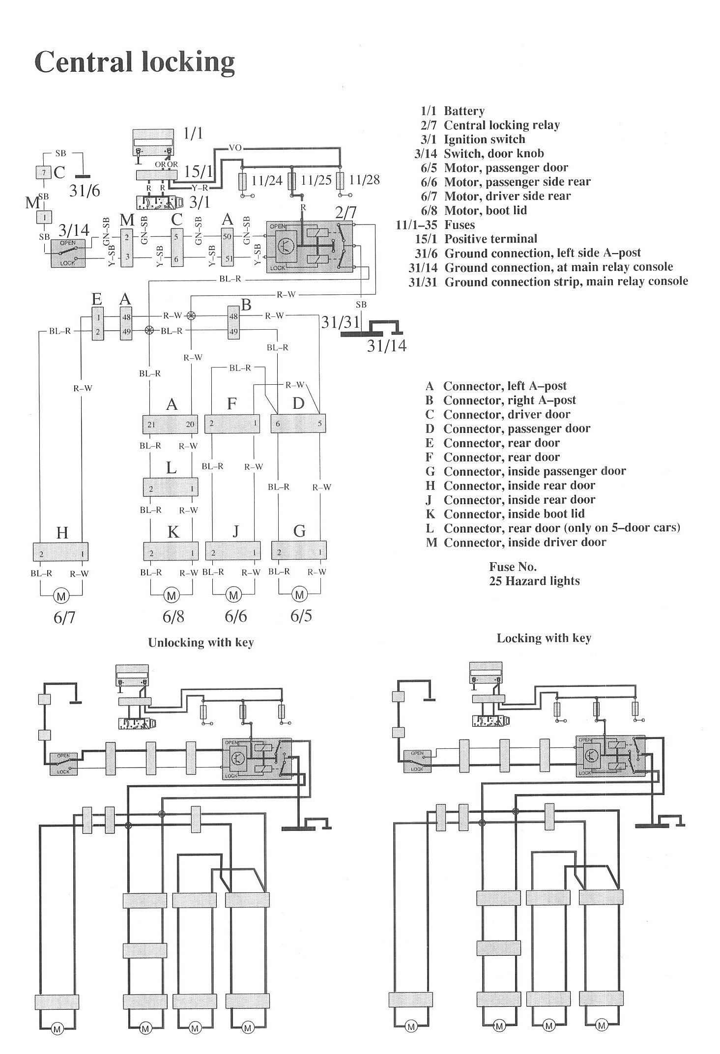
System Diagram
Wiring Diagrams:
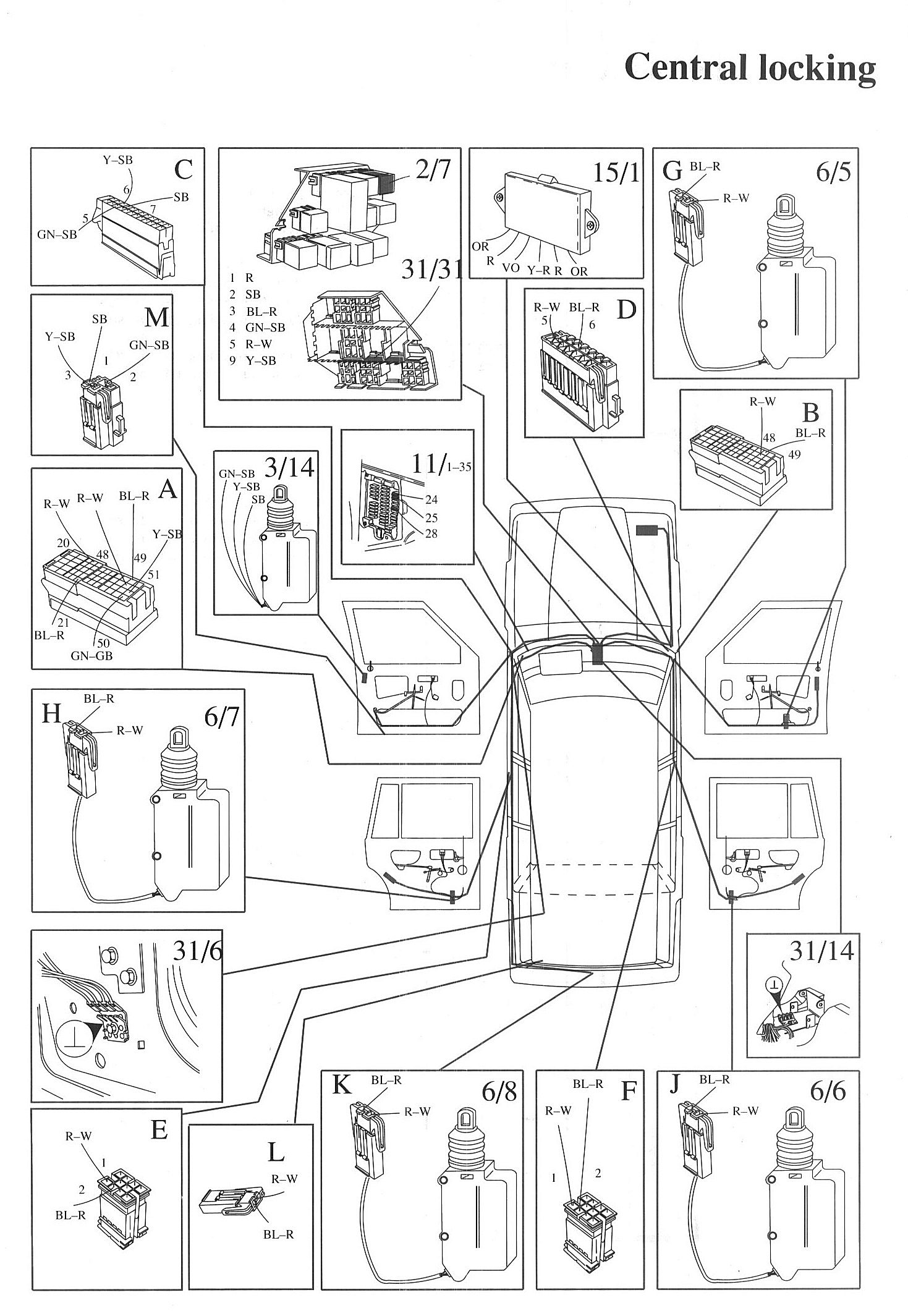
Component / Connector Locations:
LEGEND
1/1 Battery
2/7 Central locking relay
3/1 Ignition switch
3/14 Switch, door knob
615 Motor, passenger door
6/6 Motor, passenger side rear
6/7 Motor, driver side rear
6/8 Motor, boot lid
11/1-35 Fuses
15/1 Positive terminal
31/6 Ground connection, left side A-post
31/14 Ground connection, at main relay console
31/31 Ground connection strip, main relay console