Bosch
***UPDATED BY TSB 25202704, MAY 1991
Fig. 357 BASIC THROTTLE SETTING:
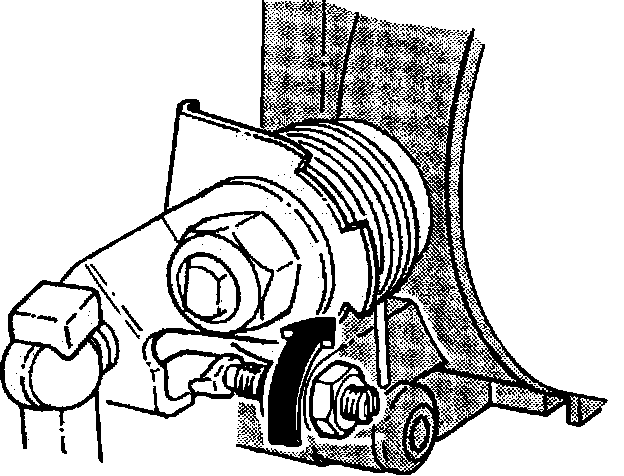
NOTE: The idle speed is controlled by an Engine Control Module (ECM). Do not attempt to adjust the idle speed. If it is out of specified tolerance (775 ± 50 RPM in P), see COMPUTERS AND CONTROL SYSTEMS.
1. Disconnect the throttle pulley link arm. Release the lock nut.
2. Loosen the adjustment screw until the throttle is fully closed.
3. Turn the adjustment screw clockwise until it just touches the link arm and then 1/4 turn more. Tighten the locking nut.
NOTE: It may be necessary to loosen the throttle switch before adjusting throttle plate.
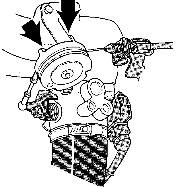
Fig. 358 CHECK TROTTLE SWITCH SETTING:

4. Check the throttle switch by opening the throttle valve slightly and listening for a "click".
5. Adjust the throttle switch by loosening the retaining screws (3 mm screw). Turn the switch slightly clockwise. Turn switch back again until "click" is heard. Tighten the retaining screws. Recheck the setting.
Fig. 359 ADJUST THROTTLE PULLEY AND CABLE:
6. Check for smooth operation of the control pulley and cable.
7. Adjust the throttle cable so it is stretched at idle, but does not affect the control pulley position. At idle the control pulley should touch the stop.
8. With the accelerator pedal fully depressed, the control pulley should touch the full throttle stop.
Fig. 362 ADJUST AUTOMATIC TRANSMISSION KICKDOWN CABLE:
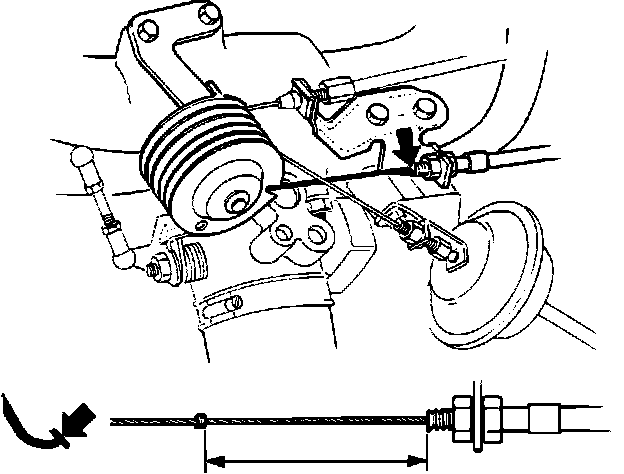
9. Check the kick-down cable (if equipped) adjustment by pressing the accelerator pedal to the floor and measuring the distance between the cable sleeve and clip. Do not operate the throttle control by hand, it can give you a wrong reading. Measurement should read 50.4 - 52.6 mm (1.98 - 2.07 in), adjust as necessary.
Fig. 360 CONNECT AND ADJUST LINK ROD:
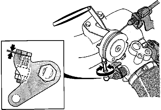
10. Connect the link rod.
11. Place a 1 mm (0.04 in) feeler gauge between the control pulley and idle speed stop. Clearance between the lower adjustment screw and the end stop should now be 0.1 mm (0.004 in). Adjust link rod as needed.