Electrical Diagrams

Wiring Diagram

Component Location
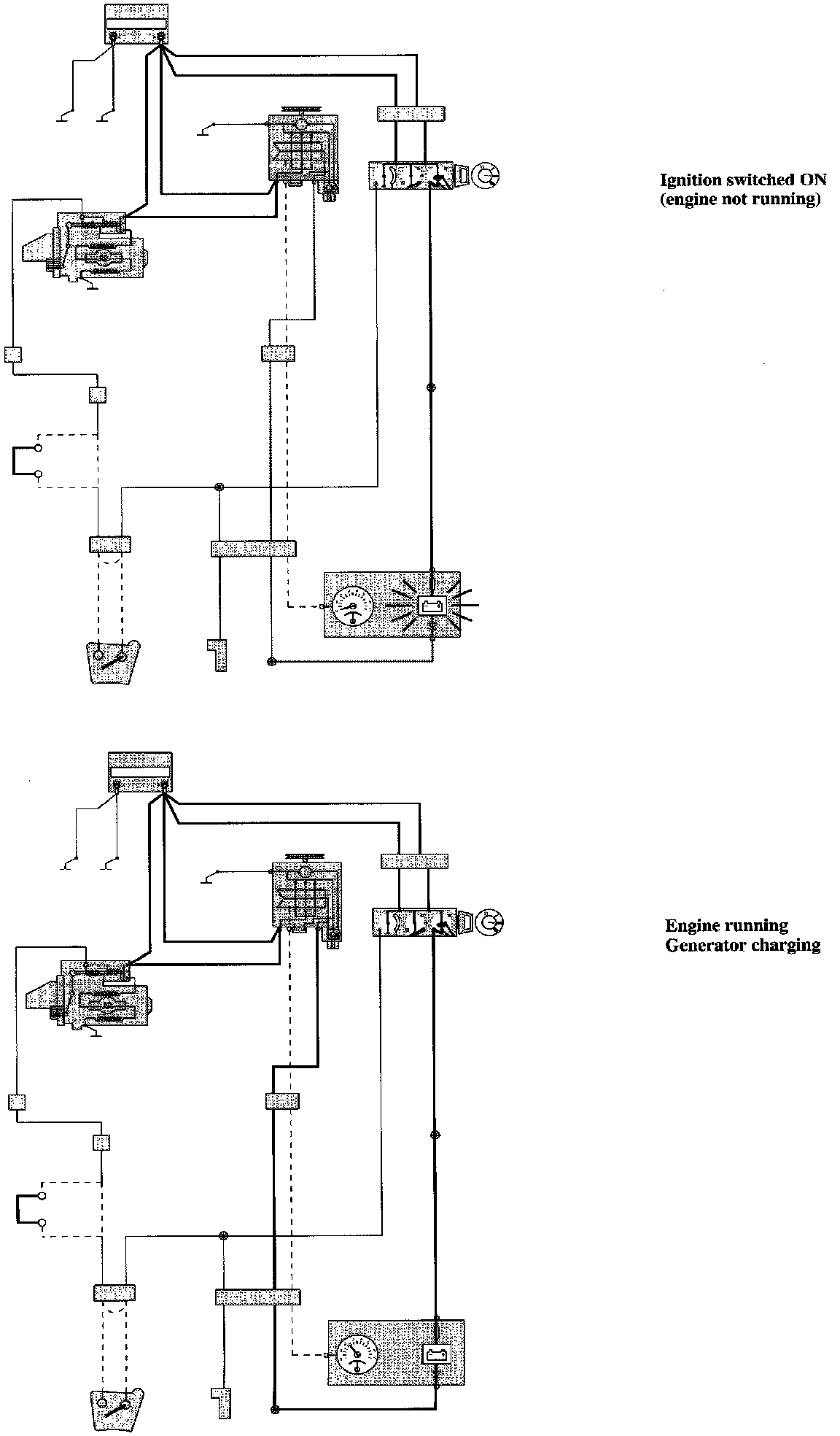
Schematic Presentation
Component I.D. List
C2 Connector, 53-pin Instrument panel harness - Left wheel housing harness
C51 Connector, 8-pin Left wheel housing harness - Engine harness
C166 Connector, at el. dist. unit, 8-pin
3/1 Ignition lock
3/40 Start inhibit switch, automatic transmission
5/1 Combined instrument
6/25 Starter motor
6/26 Generator
10/87 Indicator light, charge
11/41 Fuse, combined instrument
15/1 Positive terminal
17/1 Service data link connector for starter motor operation
19/2 Rev. counter (RPM gauge)
31/3 Ground connector body (ground connection, battery-body)
31/4 Ground connector engine (ground connection, battery-engine)
31/26 Ground connector, generator