Install. Control Module/Cable 960-S90-V90 MCC/ECC 95-97
Installing control module and cables960 MCC/ECC model year 1995-
S90/V90 MCC/ECC model year 1997-
F1
Preparations
- Clean evaporator according to Service Manual: Section 8(87)
Climate control
700/900 1982-
Section Y
- Make note of radio code if anti-theft coded radio installed.
Remove:
- Negative battery lead.
- Sound insulation on passenger side.
- Glove compartment.
Refer to Service Manual:
Section 8(82-86, 88) Interior, exterior 700/900 1982-
Cable connections

F2
Installing new relay on cable harness
Take out cable harness, P/N 9171004-6, included in kit.
- Install 3 relays included in the 5-pin connector.

F3
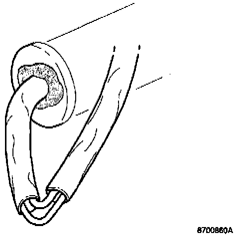
Route cables to engine compartment
- Route the cables which do not have connectors to the engine compartment through an unused hole in the grommet under the brace to the suspension strut.
- Connect green-red cable to connector terminal 1.
- Connect green cable to connector terminal 2.

F4
- Separate existing connectors at the boost pressure switch and connect connector from the new cable harness.
F5
Location of cable sheath opening
The cable sheath is cut to drain off condensation.
- The cut conduit section should be placed at the lowest point along the route of the cable.
- Use butyl tape to seal the grommet.
- Use existing cable tie to clamp cables to firewall.
Connecting cable harness in passenger compartment

F6
Connect white 6-pin cable harness connectors
The new cable harness should be connected between the existing connectors on the climate unit - passenger compartment cable harnesses, (All in wiring diagram).

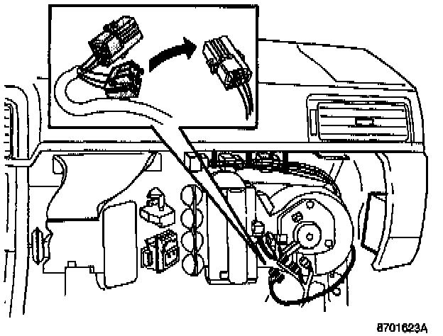
F7
Connect 2-pin cable harness connectors
The new 2-pin cable harness connectors should be connected between the blower motor and the existing cable harness, (6128 in wiring diagram).
F8
Connect 4-pin cable harness connectors
The new 4-pin cable harness connectors should be connected to the accessory connectors (D10 in wiring diagram).

If there are accessories connected to the accessory cabling, the new cable harness connectors should be connected between the existing ones.
Installing control module from kit

F9
Connecting and mounting control module in cars without SRS (Airbag) and knee bolster
- Connect control module and cable harness connectors.
- Apply three sections of butyl tape to the control module.
- Install control module to dashboard side section with butyl tape.

F10
Fastening cables In cars without SRS (Airbag) and knee bolster
- Fasten cable harness and relay to the air hose that runs above the glove compartment to the side defroster with cable ties.

F11
Connecting and mounting control module in cars with SRS (Airbag) and knee bolster
- Install control module on front of air hose under glove compartment with butyl tape and cable ties round duct and control module as illustrated.
- Locate cable harness with relays between air hose and knee bolster.
NOTE:
Prevent condensation dropping onto relays by ensuring that they are not placed beneath the air hose.
- Fasten to air hose with cable ties.
Installing control module from kit.

F12
Function verification and information
Check airing cycle is working
- Connect battery lead and start car.
- Turn on A/C system to start compressor. The A/C system starts if the temperature exceeds approx. 7°C (45°F).
- Make up a cable (about 2 meters in length) to connect battery positive terminal to the connector on the control module. Connect to green cable, connector terminal 6, for at least 30 seconds while compressor is running.
- Turn off engine.
Airing cycle should begin after approximately 10 seconds and continue for approximately 1 second.
- Remove cable between connector and battery.
F13
Finishing off
- Reinstall all components removed.
- Reset the clock and enter the anti-theft radio code if required.
F14
Information to Car Owner
Carry out operations at the end of this service bulletin.