Installing Control Module and Cables/740 MCC 1988-90
Installing control module and cables 740 MCC model year 1988-90A1
Preparations
- Clean evaporator according to Service Manual:
Section 8(87)
Climate control
700/900 1982-
Section Y
- Make note of radio code if anti-theft coded radio installed.
Remove:
- Negative battery lead.
- Sound insulation on passenger side.
- Glove compartment.
- Cowl on passenger side.
- Ashtray.
- Cigarette lighter.
- Storage compartment.
- Detach, pull out and turn central electronics module.
See section 37 in Service Manuals:
Section 3(35-39)
Lighting, instrumentation and
other electrical equipment
700/900 1982-
Section 8(82-86,88)
Interior, exterior
700/900 1982-

Cable connections
A2
Installing new relay on cable harness
- Take out cable harness (P/N 9148755) supplied with kit.
- Connect the relay in the kit to the 5-pin connector which is attached to the same end of the cable harness as the black-red cable.

A3
Attaching new cable harness with relay
- Connect relay and cable harness above the heater vacuum reservoir, using a cable tie.
- Route the red-black cable inside the centre console right side panel to the central electronics module.
- Connect cable to central electronics module fuse 6 and terminal 4.
- Use cable tie to attach to existing cable harness.

A4
Removing existing connector from existing cable harness
- Disconnect 5-pin connector from blower relay (relay 131 in the Service Manual).
See Service Manual:
Section 3 (39)
Wiring diagrams
740 1990

A5
Cable terminal, opening
- Detach the cables carefully from the connector's receptacle housing using tool 9814229-2, from repair kit 9814235.
See Service Manual:
Section 3(37),
Wiring repairs and replacing cable terminals
850, 900

A6
Installation of 5 housing receptacles
- Straighten the locking tongues carefully and attach the 5 white housing receptacles from the kit.

A7
Connecting the new cable harness to the 5 housing receptacles
- Attach housing receptacles to the cable harness tab terminals according to cable colour coding (colour-to-colour match)

A8
Connecting new cable harness to blower relay
- Connect the 5-pin cable harness connector to the blower relay.
See Service Manual:
Section 3 (39)
Wiring diagrams
740 1990

A9
Connection of cable to ground plate
- Connect the black-white cable included in the new cable harness to the ground plate on the right side of the cowl.
The ground plate is located behind the fuel control module.

A10
Route cables to engine compartment
- Route the green cables on the cable harness to the engine compartment through the vacant hole in the grommet under the brace to the suspension tower.
1988 and 1989 model years:
- Connect the flat connectors.
Year model 1990 cars (shown here):
- Connect the round connectors.
- Connect all unconnected connectors to each other.
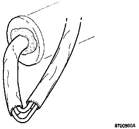
A11
Location of cable sheath opening
The cable sheath is cut to drain off condensation.
- The cut conduit section should be placed at the lowest point along the route of the cable.
- Use butyl tape to seal the grommet.
- Use existing cable tie to clamp cables to firewall.

Installing control module from kit
A12
Connection and mounting of control module
- Connect cable harness connector to control module connector.
- Apply three sections of butyl tape to the control module.
- Install control module on dashboard side section with butyl tape.

A13
Installation of cable harness
- Arrange cable harness as shown.
- Fasten the new cable harness using cable tie on the existing cable harness ensuring that the harness cannot come into contact with the heater shutter spindle.
Function verification and information
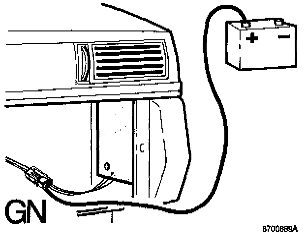
A14
Check airing cycle is working
- Connect battery lead and start car.
- Turn on A/C system so that the compressor starts. The A/C system starts if the temperature exceeds approx. 7°C (45°F).
- Make up a cable (about 2 meters (6 ft.) in length) to connect battery positive terminal to the connector on the control module. Connect to green cable, connector terminal 6, for at least 30 seconds while compressor is operating.
- Turn off engine.
Airing cycle should begin after approximately 10 seconds and continue for approximately 1 second. - Remove cable between connector and battery.
A15
Finishing off
- Reinstall all components removed.
- Reset the clock and enter the anti-theft radio code if required.
A16
Information to car owner
- Carry out operations at the end of this service bulletin.