5.2L BXA Overviews
Engine Management System
5.2L BXA Overviews
Engine Compartment Right
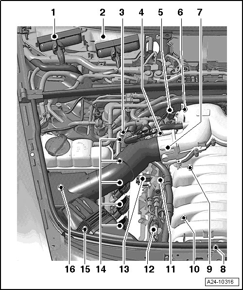
1 Engine Control Module (ECM) 2 -J624- => [ Engine Control Modules ] See Image Below.
2 Engine Control Module (ECM) -J623- => [ Engine Control Modules ] See Image Below.
3 Camshaft Adjustment Valve 1 (exhaust) -N318- => [ Location on Right Cylinder Bank 1 ] See Image Below.
4 Camshaft Adjustment Valve 1 -N205- => [ Location inside cylinder head ] See Image Below.
5 Low Fuel Pressure Sensor -G410- => [ Installation Locations from Top ] See Image Below.
6 Engine Coolant Temperature (ECT) Sensor -G62- => [ Engine from Behind ] See Image Below.
7 Throttle Valve Control Module -J338- => [ Installation Locations from Top ] See Image Below.
8 Components on Front of Engine => [ Engine viewed from front ] See Image Below.
• Intake Manifold Runner Position Sensor -G336-
• Variable Intake Manifold Runner Motor -V183-
• Intake Flap Motor -V157-
• Secondary Air Injection (AIR) Solenoid Valve -N112-
• Intake Manifold Runner Position Sensor 2 -G512-
• Oil Pressure Switch -F1- / -F22-
9 Knock Sensor 2 -G66- => [ Location inside cylinder head ] See Image Below.
10 Knock Sensor 1 -G61- => [ Location inside cylinder head ] See Image Below.
11 High Pressure Pump
• With Fuel Metering Valve -N290-
12 Camshaft Position (CMP) Sensor -G40- => [ Location on Right Cylinder Bank 1 ] See Image Below.
13 Fuel Metering Valve -N290- electrical connector
14 Ignition Coils, Cylinder Bank 1 -N70-, -N127-, -N291-, -N292- and -N323-
15 Camshaft Position (CMP) Sensor 3 -G300- => [ Location on Right Cylinder Bank 1 ] See Image Below.
16 Mass Air Flow (MAF) Sensor -G70- / Intake Air Temperature (IAT) Sensor -G42-
5.2L BXA Engine Compartment Left
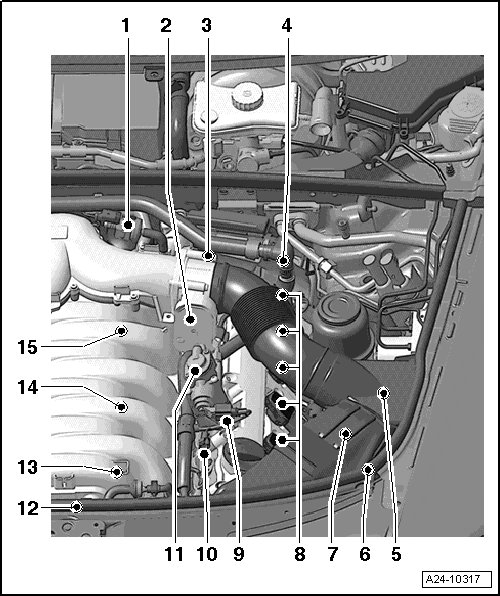
1 Evaporative Emission (EVAP) Canister Purge Regulator Valve 1 -N80- => [ Installation Locations from Top ] See Image Below.
2 Throttle Valve Control Module 2 -J544- => [ Installation Locations from Top ] See Image Below.
Throttle Valve Control Module 2 is integrated with the following:
• Throttle Drive 2 -G296-
• Throttle Drive Angle Sensor 1 -G297-
• Throttle Drive Angle Sensor 2 -G298-
3 Camshaft Adjustment Valve 2 -N208- => [ Location on left cylinder bank 2 ] See Image Below.
4 Camshaft Adjustment Valve 2 (exhaust) -N319- => [ Location on left cylinder bank 2 ] See Image Below.
5 Mass Air Flow (MAF) Sensor 2 -G246-
• Integrated with Intake Air Temperature (IAT) Sensor 2 -G299-
6 Secondary Air Injection (AIR) Pump Motor -V101- => [ Secondary Air Injection (AIR) Pump Motor ] See Image Below.
7 Camshaft Position (CMP) Sensor 4 -G301- => [ Location on left cylinder bank 2 ] See Image Below.
8 Ignition Coils Cylinder Bank 2 -N324-, -N325-, -N326-, -N327- and -N328-
9 Fuel Metering Valve 2 -N402- electrical connector
10 Camshaft Position (CMP) Sensor 2 -G163- => [ Location on left cylinder bank 2 ] See Image Below.
11 High Pressure Pump
• With Fuel Metering Valve 2 -N402-
12 Components on Front of Engine => [ Engine viewed from front ] See Image Below.
• Intake Manifold Runner Position Sensor -G336-
• Variable Intake Manifold Runner Motor -V183-
• Intake Flap Motor -V157-
• Secondary Air Injection (AIR) Solenoid Valve -N112-
• Intake Manifold Runner Position Sensor 2 -G512-
• Oil Pressure Switch -F1- / -F22-
13 Fuel Pressure Sensor -G247- => [ Location inside cylinder head ] See Image Below.
14 Knock Sensor 3 -G198- => [ Location inside cylinder head ] See Image Below.
15 Knock Sensor 4 -G199- => [ Location inside cylinder head ] See Image Below.
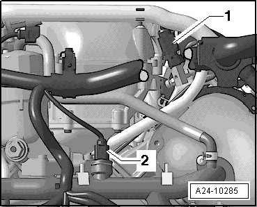
Engine Control Modules
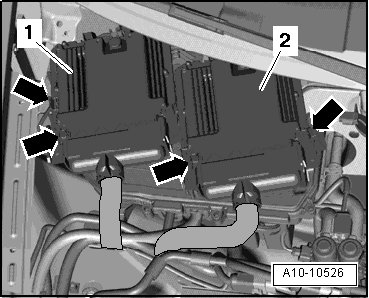
1 - Engine Control Module (ECM) 2 -J624- (slave)
2 - Engine Control Module (ECM) -J623- (master)
Installation Locations from Top
1 - Low Fuel Pressure Sensor -G410-
2 - Evaporative Emission (EVAP) Canister Purge Regulator Valve 1 -N80-
3 - Throttle Valve Control Module 2 -J544-
4 - Throttle Valve Control Module -J338-
Engine from Behind
1 - Low Fuel Pressure Sensor -G410-
2 - Engine Coolant Temperature (ECT) Sensor -G62-
Engine Speed (RPM) Sensor
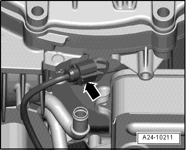
Engine Speed (RPM) Sensor -G28-
Engine viewed from front
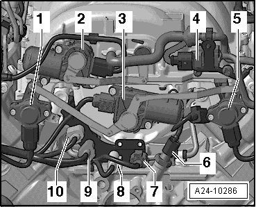
1 - Intake Manifold Runner Position Sensor -G336-
2 - Variable Intake Manifold Runner Motor -V183-
3 - Intake Flap Motor -V157-
4 - Secondary Air Injection (AIR) Solenoid Valve -N112-
5 - Intake Manifold Runner Position Sensor 2 -G512-
6 - Oil Pressure Switch -F1- / -F22-
7 - Connector for Knock Sensor 4 -G199-
8 - Connector for Knock Sensor 3 -G198-
9 - Connector for Knock Sensor 1 -G61-
10 - Connector for Knock Sensor 2 -G66-
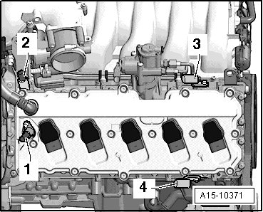
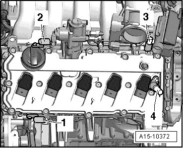
Location inside cylinder head
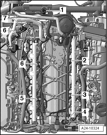
1 - Engine Coolant Temperature (ECT) Sensor -G62-
2 - Knock Sensor 4 -G199-
3 - Knock Sensor 3 -G198-
4 - Fuel Pressure Sensor -G247-
5 - Knock Sensor 1 -G61-
6 - Knock Sensor 2 -G66-
7 - Camshaft Adjustment Valve 1 -N205-
8 - Low Fuel Pressure Sensor -G410-
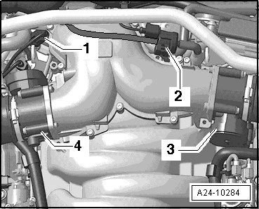
Location on Right Cylinder Bank
1
1 - Camshaft Adjustment Valve 1 (exhaust) -N318-
2 - Camshaft Adjustment Valve 1 -N205-
3 - Camshaft Position (CMP) Sensor -G40-
4 - Camshaft Position (CMP) Sensor 3 -G300-
Location on left cylinder bank
2
1 - Camshaft Position (CMP) Sensor 4 -G301-
2 - Camshaft Position (CMP) Sensor 2 -G163-
3 - Camshaft Adjustment Valve 2 -N208-
4 - Camshaft Adjustment Valve 2 (exhaust) -N319-
Fuel Injectors (left cylinder shown)

Arrow - Fuel Injectors -N30-, -N31-, -N32-, -N33-, -N83-, -N84-, -N85-, -N86-, -N299- and -N300-
Secondary Air Injection (AIR) Pump
Motor

1 - Secondary Air Injection (AIR) Pump Motor -V101-
Below left long member
Battery Monitoring Control Module
(if applicable)

2 - Electrical connector
3 - Battery Monitoring Control Module -J367-