Power Windows Malfunction
Power Windows Malfunction
Diagnostic Instructions
* Perform the Diagnostic System Check - Vehicle (Initial Inspection and Diagnostic Overview) prior to using this diagnostic procedure.
* Review Strategy Based Diagnosis (Initial Inspection and Diagnostic Overview) for an overview of the diagnostic procedure.
* Diagnostic Procedure Instructions (Initial Inspection and Diagnostic Overview) provide an overview of each diagnostic category.
Diagnostic Fault Information
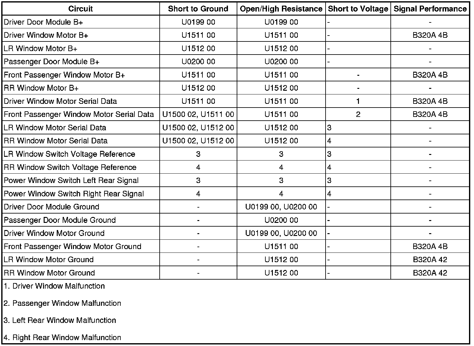
Circuit/System Description
The front and rear power windows are controlled by the driver door module (DDM) and front passenger door module (PDM). The DDM and PDM each contain power window switches that are integrated into the module. The DDM contains the master power window switch that controls all power window operations. The DDM supplies the left rear power window switch with a 12 volt reference and signal circuit. The power window switch contained in the PDM controls the front passenger window operation only. The PDM supplies the right rear power window switch with a 12-volt reference and signal circuit.
When the driver power window switch is activated to a desired position, the DDM examines the request and checks for messages from other vehicle control modules prohibiting window movement. If no prohibitive messages have been received, the DDM will send a serial data message to the driver door window motor to move the window to the desired position.
When the DDM receives a request to operate one of the right side passenger windows from the driver master control, a serial data message is sent to the PDM. The PDM examines the request and checks for messages from other vehicle control modules prohibiting the window movement. If no prohibitive messages have been received, the PDM will send a serial data message to the appropriate window motor to move the window as requested.
The DDM and PDM supply their respective rear power window switches with a 12 volt reference and signal circuit. The rear power window switches contain separate resistors for each switch position. When a rear power window switch is activated, the associated door control module interprets the signal and checks for messages from other vehicle control modules prohibiting the window movement. If no prohibitive messages have been received, the door control module sends a serial data message to the appropriate power window motor commanding the requested window position.
Diagnostic Aids
A short to ground on the B+ voltage reference circuits to the rear power window switches will cause the door control module to stop supplying the B+ voltage reference even after the fault is no longer present. When this condition exists, the corresponding door control module fuse may have to be removed to reset the door control module.
Reference Information
Schematic Reference
Moveable Window Schematics ([1][2]Electrical Diagrams)
Connector End View Reference
Component Connector End Views (Connector Views)
Description and Operation
Power Windows Description and Operation (Power Windows Description and Operation)
Electrical Information Reference
* Circuit Testing (Component Tests and General Diagnostics)
* Connector Repairs (Component Tests and General Diagnostics)
* Testing for Intermittent Conditions and Poor Connections (Component Tests and General Diagnostics)
* Wiring Repairs (Component Tests and General Diagnostics)
Scan Tool Reference
Control Module References (Programming and Relearning) for scan tool information
Circuit/System Verification
1. Ignition ON, observe the scan tool Driver LF Window Switch, Driver RF Window Switch, Driver LR Window Switch and Driver RR Window Switch parameters while using each window switch on the driver master control. The parameters should change from Off, Up, Down, Express Up, and Express Down.
• If the values do not change, replace the DDM.
2. Observe the scan tool Passenger Window Switch parameters while using the front passenger window switch. The parameters should change from Off, Up, Down, Express Up, and Express Down.
• If the values do not change, replace the PDM.
3. Observe the operation of each power window while commanding each window UP and DOWN by using the power window switches on each door. Each power window should perform the UP and DOWN function.
• If either rear passenger power window switch is inoperative, refer to Rear Passenger Window Switch Malfunction.
• If a power window does not perform the UP or DOWN function, refer to Power Window Motor Malfunction.
Circuit/System Testing
Rear Passenger Window Switch Malfunction
1. Ignition OFF, disconnect the harness connector at the appropriate rear window switch.
2. Ignition ON, test for less than 5 ohms between the signal circuit terminal 4 and ground.
• If greater than the specified range, test the signal circuit for a short to voltage or an open/high resistance. If the circuit tests normal, replace the appropriate door module.
3. Test for greater than 10 volts between the reference circuit terminal 3 and ground.
• If less than the specified value, test the reference circuit for a short to ground or and open/high resistance. If the circuit tests normal replace the door module.
4. If all circuits test normal, test or replace the rear window switch.
Power Window Motor Malfunction
1. Ignition OFF, disconnect the harness connector at the appropriate window motor.
2. Test for less than 5 ohms between the ground circuit terminal 4 and ground.
• If greater than the specified range, test the ground circuit for an open/high resistance.
3. Ignition ON, verify that a test lamp illuminates between the B+ circuit terminal 1 and ground
• If the test lamp does not illuminate, test the B+ circuit for a short to ground or an open/high resistance.
4. Ignition OFF, connect the harness connector at the power window motor.
5. Ignition ON, observe the scan tool Window Motor Fault Status parameter while using the power window switch, the parameter should be No Fault.
• If the parameter is Not Normalized, perform the Window Regulator Motor Programming and Setup (Programming and Relearning). If the power window motor cannot be reprogrammed, replace the power window motor
• If the parameter is Motor Fault, Hall Fault, Memory Fault, LIN Fault, Anti-Trap Fault or Thermo Active, replace the power window motor.
6. If all circuits test normal, replace the window motor.
Component Testing
Rear Window Switch
1. Ignition OFF, disconnect the harness connector at the appropriate rear window switch.
2. Test for 8.0K-9.0K ohms between the signal terminal 4 and the voltage reference terminal 3 with the switch in the inactive position.
• If not the specified value, replace the rear window switch.
3. Test for 2.75K-3.75K ohms between the signal terminal 4 and the voltage reference terminal 3 with the switch in the Auto DOWN position.
• If not the specified value, replace the rear window switch.
4. Test for 5.25K-6.25K ohms between the signal terminal 4 and the voltage reference terminal 3 with the switch in the DOWN position.
• If not the specified value, replace the rear window switch.
5. Test for 1.9K-2.9K ohms between the signal terminal 4 and the voltage reference terminal 3 with the switch in the UP position.
• If not the specified value, replace the rear window switch.
Repair Instructions
Perform the Diagnostic Repair Verification (Verification Tests) after completing the diagnostic procedure.
* Front Side Door Window Regulator Replacement (Service and Repair)
* Rear Side Door Window Regulator Replacement (Service and Repair)
* Rear Side Door Window Switch Replacement (Rear Side Door Window Switch Replacement)
* Control Module References (Programming and Relearning) for DDM or PDM replacement, setup, and programming