Removal and Replacement
Transmission Replacement
Tools Required
J 28467-B (DW-110-060) Universal Engine Support Fixture
Removal Procedure
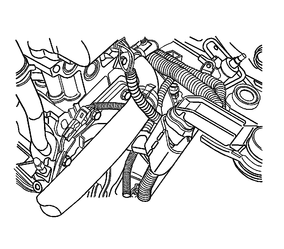
Notice:
When removing or installing the backup lamp switch, do not use an open end wrench. Use only a socket in order to avoid damage to the switch assembly.
1. Disconnect the backup lamp switch electrical connector.
2. Disconnect the speedometer speed sensor electrical connector.
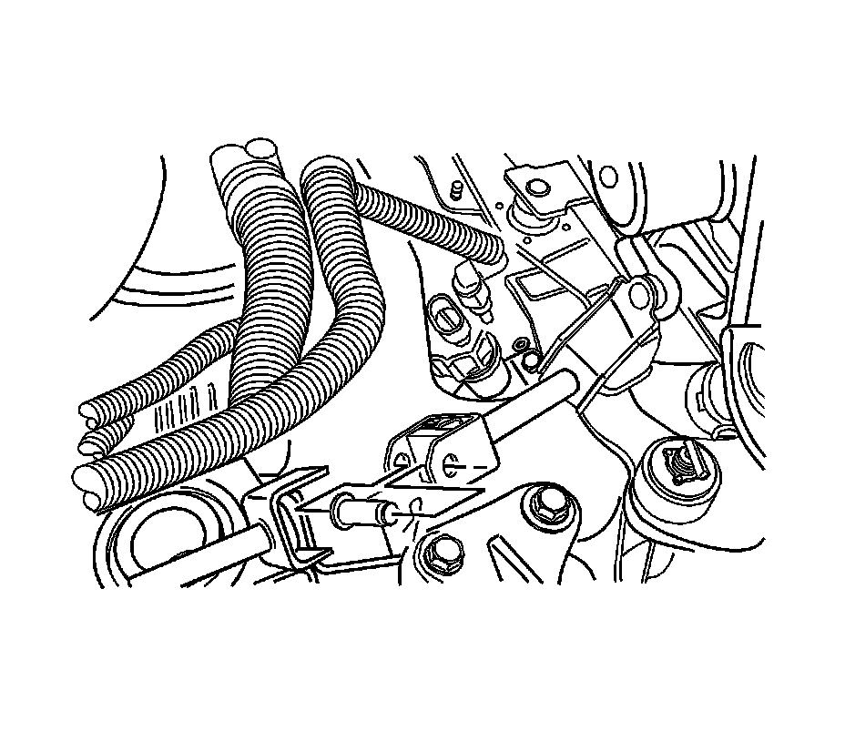
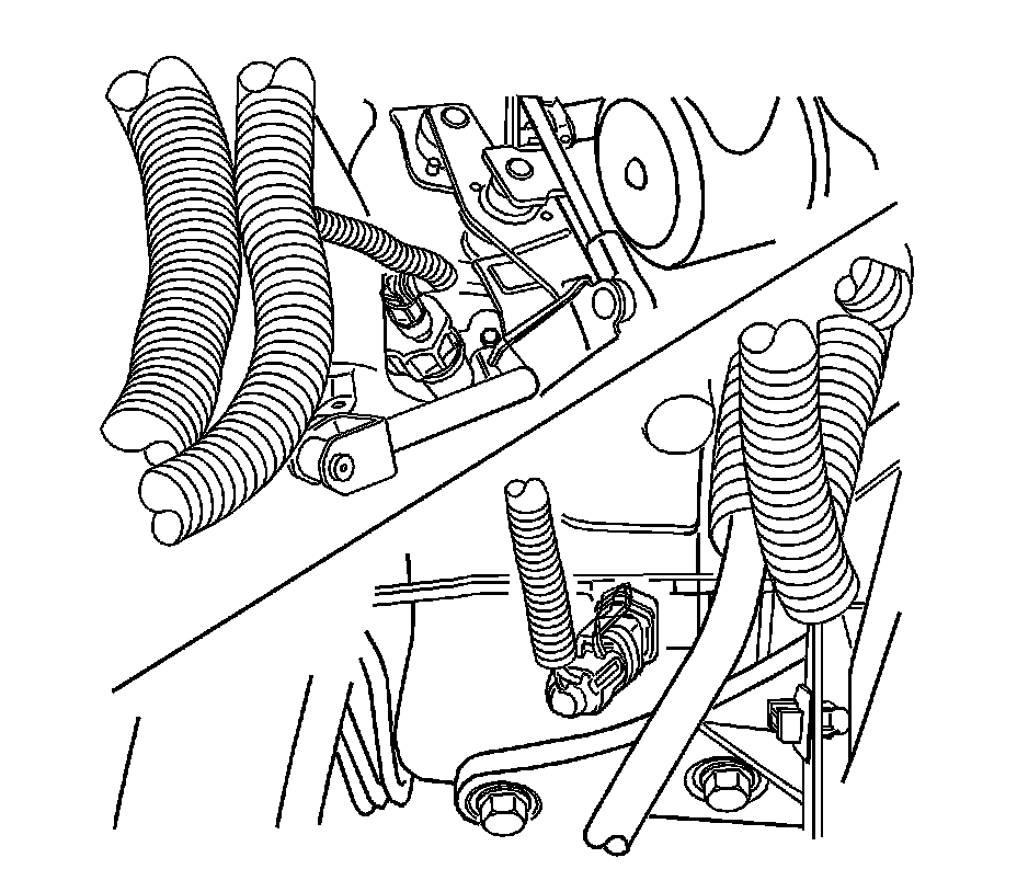
3. Remove the clip and the bolt from the universal joint.
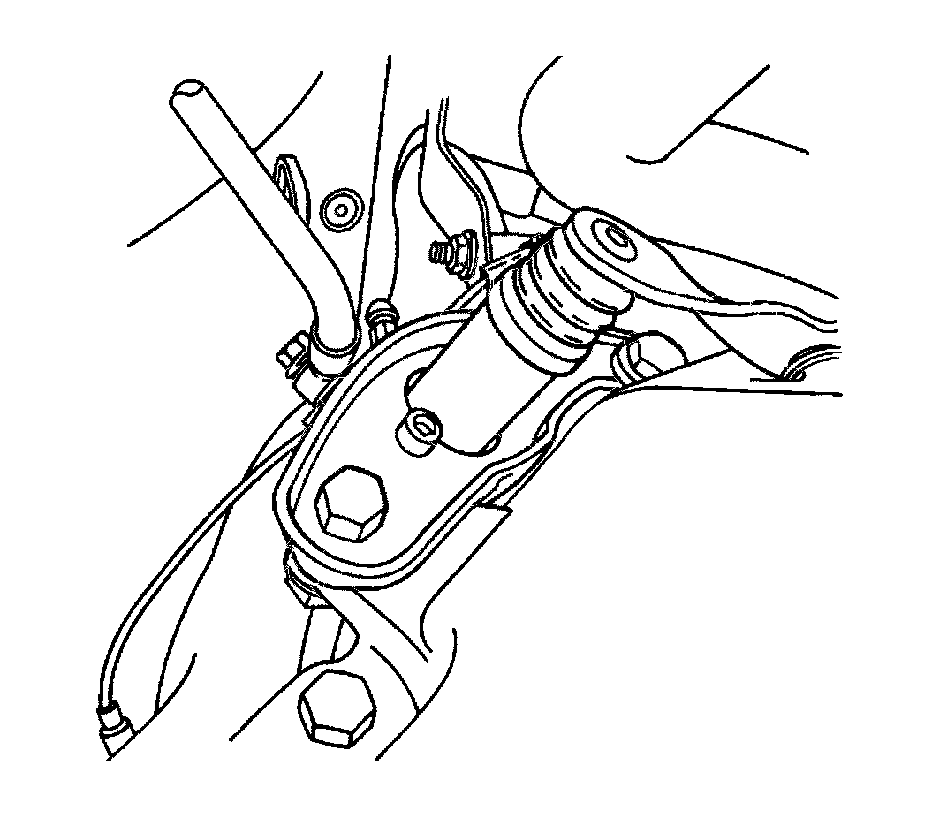
4. Remove the clutch release cylinder bracket bolts and the clutch release cylinder bracket.
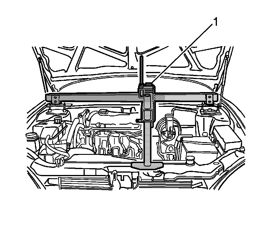
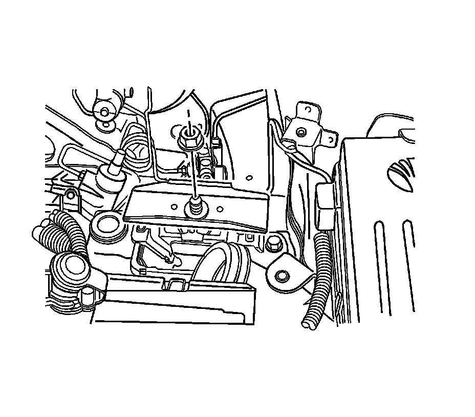
5. Install the J 28467-B (1).
6. Remove the transaxle-to-engine upper bolts.
7. Remove the left front transaxle mounting bracket nut.
8. Raise and suitably support the vehicle. Refer to Lifting and Jacking the Vehicle Service and Repair.
9. Remove both of the drive axle shafts. Refer to Front Drive Axle Inner Shaft Replacement Service and Repair.
10. Support the transaxle with a transaxle support jack.
11. Remove the crossmember. Refer to Front Suspension Crossmember Replacement Front Suspension.
12. Remove the exhaust pipe nuts. Refer to Front Pipe Replacement (2.5L) Service and Repair.
13. Remove the front transaxle mounting bracket bolts and nut.
14. Remove the rear transaxle mounting bracket bolts and bracket.
15. Remove the transaxle-to-engine lower bolts.
16. Slide the transaxle sideways away from the engine block.
17. Lower the transaxle.
Installation Procedure
Caution: Use care when cleaning the clutch hub. The clutch hub may have sharp edges and can cause personal injury if contact is made. Wear protective gloves to avoid personal injury.
1. Clean the clutch hub and the input shaft from any debris and contaminates with a lint-free towel.
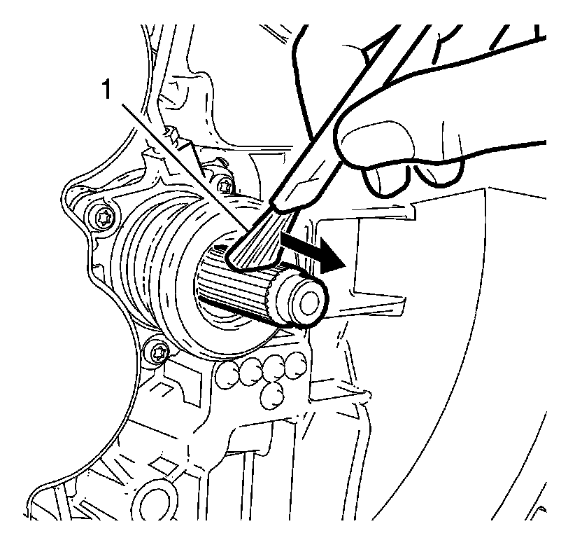
Notice: Applying too much or the wrong type of grease on the transmission input shaft may cause damage, clutch slippage or failure. Always apply the correct type of grease. Never apply more grease than is necessary to coat the transmission input shaft with a very thin film of grease.
2. Use a clean flat brush (1) to apply very light coating of multi-purpose grease to input shaft until the metal is only shiny. No visible clumps of grease are permissible regardless of size. Smear away from the transmission in direction of the shown arrow.
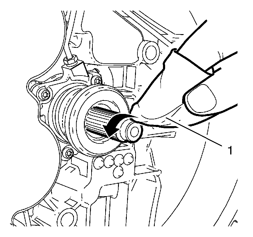
Notice: Ensure that no grease remains on the lead surface of the transmission input shaft. Clean the lead surface of the transmission input shaft prior to the assembly of the transmission to the engine. Failure to maintain a clean surface may cause clutch slippage or failure.
3. Clean the entire lead surface of the input shaft with a NEW, lint-free towel (1).
4. Support the transaxle with a transaxle support jack.
5. Install the transaxle by inserting the transaxle input shaft into the clutch disc and sliding the transaxle sideways into the engine block.
Notice: Refer to Fastener Notice Fastener Notice.
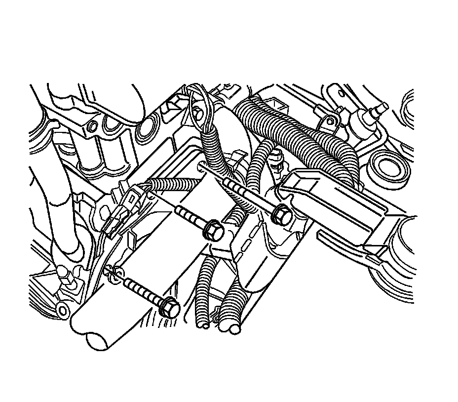
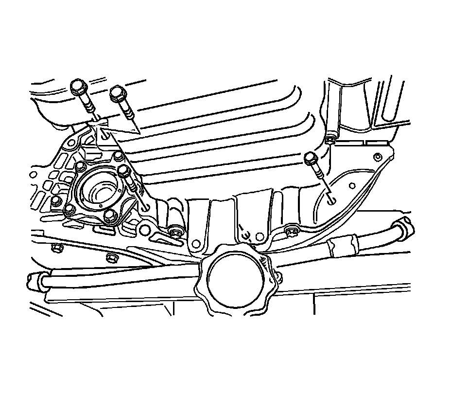
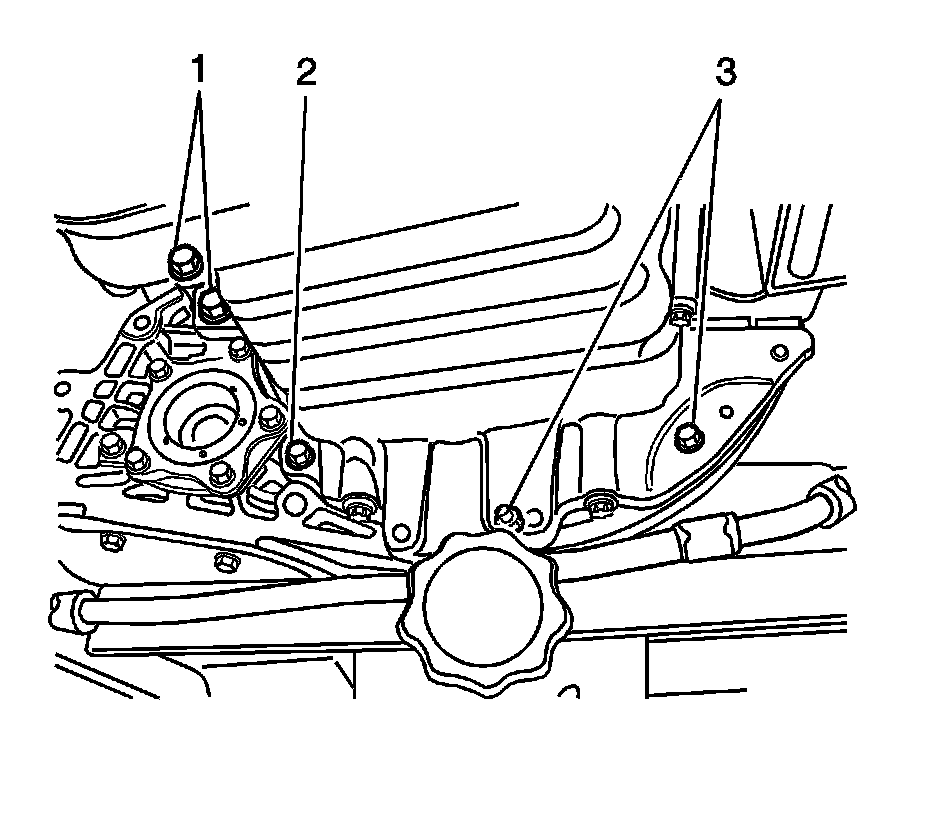
6. Install the transaxle-to-engine lower bolts.
* Tighten the transaxle-to-engine lower bolts (1) to 75 Nm (55 lb ft).
* Tighten the transaxle-to-engine lower bolt (2) to 21 Nm (15 lb ft).
* Tighten the transaxle-to-engine lower bolts (3) to 31 Nm (23 lb ft).
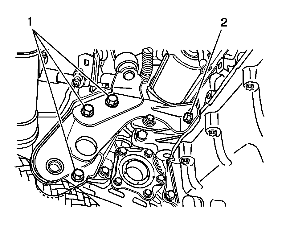
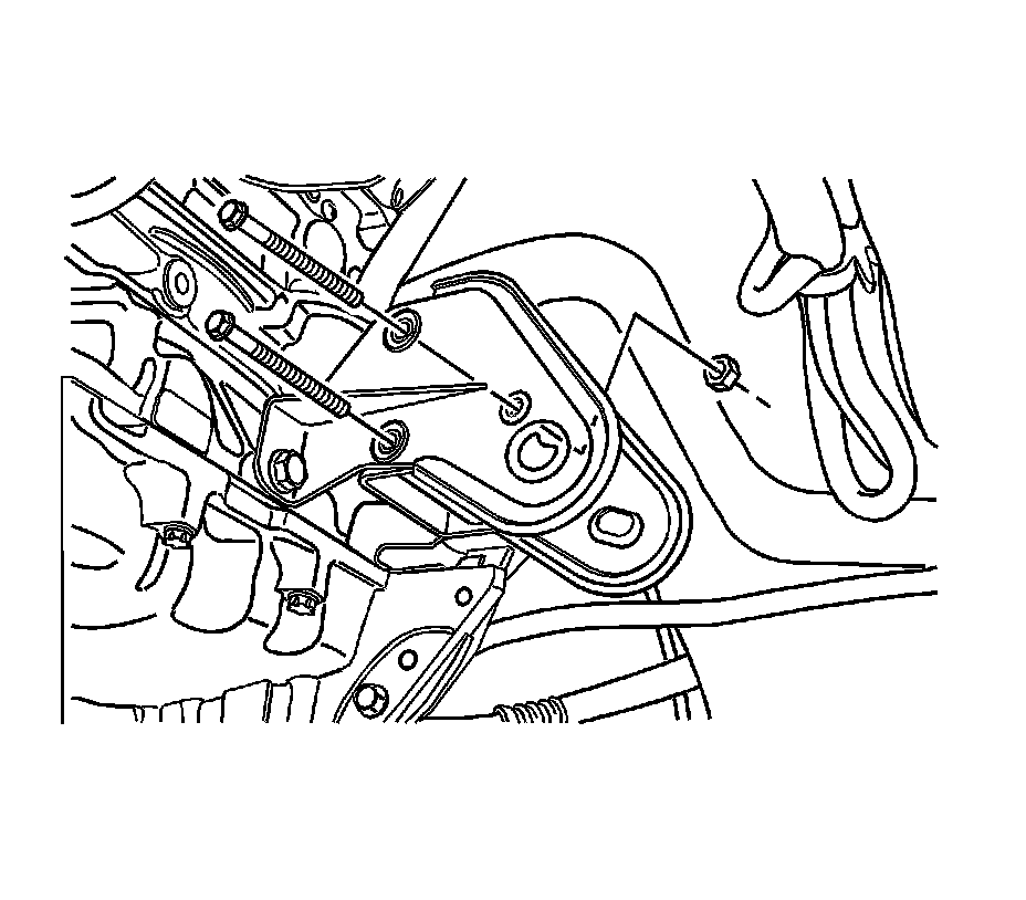
7. Install the rear transaxle mounting bracket and the bolts.
* Tighten the rear transaxle mounting bracket bolts (1) to 90 Nm (66 lb ft).
* Tighten the rear transaxle mounting bracket bolt (2) to 65 Nm (48 lb ft).
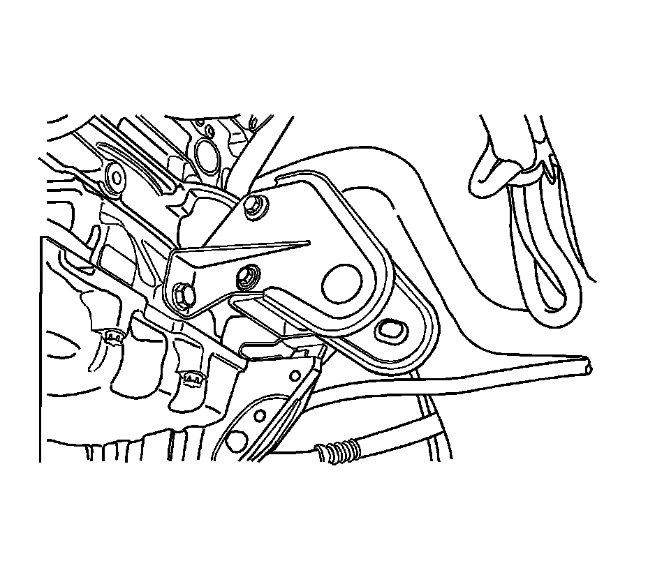
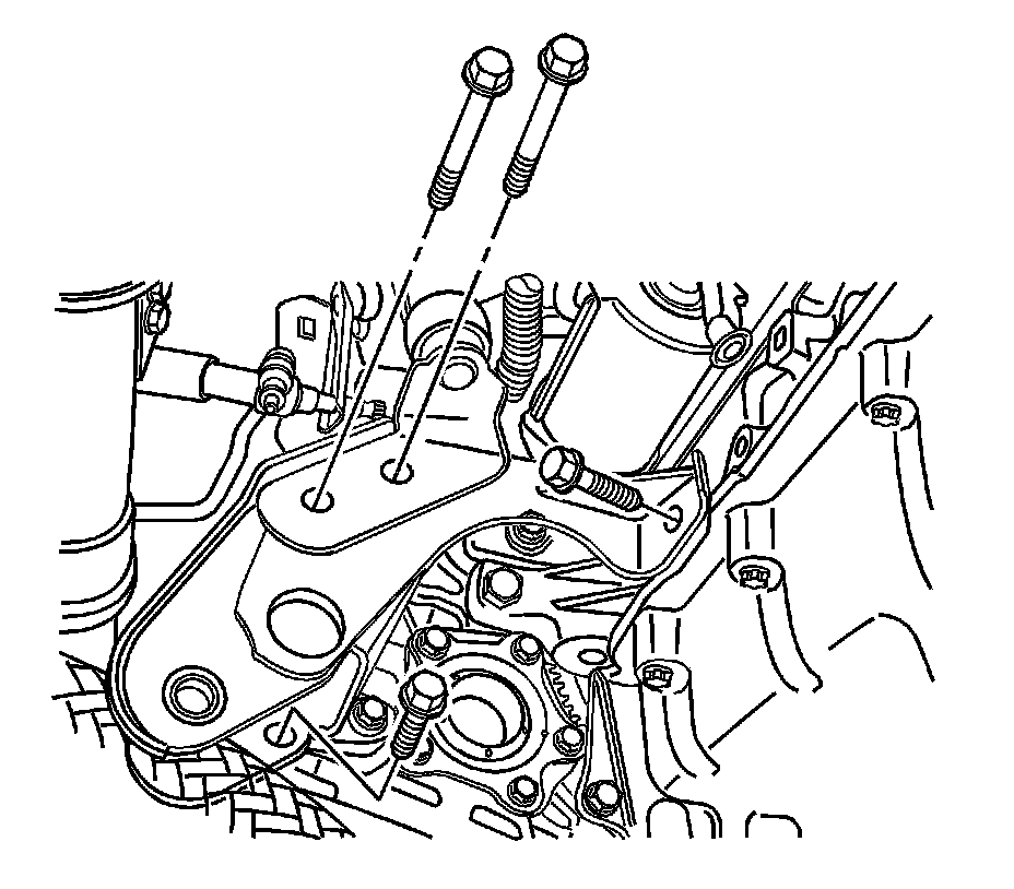
8. Install the front transaxle mounting bracket bolts and the nut.
Tighten the front transaxle mounting bracket bolts and nut to 90 Nm (66 lb ft).
9. Install the exhaust pipe nuts. Refer to Front Pipe Replacement (2.5L) Service and Repair.
10. Install the crossmember. Refer to Front Suspension Crossmember Replacement Front Suspension.
11. Install the drive axles. Refer to Front Drive Axle Inner Shaft Replacement Service and Repair.
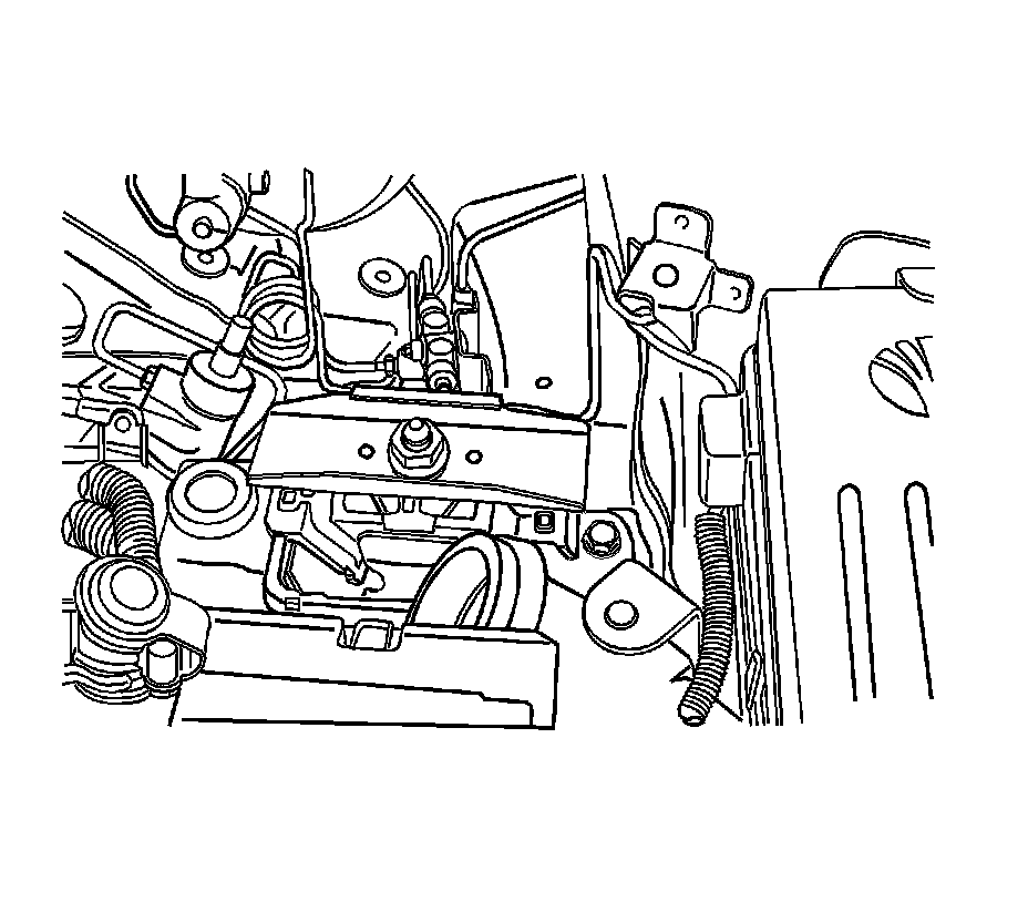
12. Install the left front transaxle mounting bracket nut.
Tighten the nut to 155 Nm (114 lb ft).
13. Install the upper transaxle-to-engine bolts.
Tighten the transaxle-to-engine upper bolts to 75 Nm (55 lb ft).
14. Remove the J 28467-B (1).
15. Install the clutch release cylinder bracket and the clutch release cylinder bracket bolts.
Tighten the clutch release cylinder bracket bolts to 75 Nm (55 lb ft).
16. Install the bolt and the clip onto the universal joint.
17. Connect the speedometer speed sensor electrical connector.
18. Connect the backup lamp switch electrical connector.
19. Inspect the fluid level. Refer to Transmission Fluid Level Inspection Testing and Inspection.