ABS Indicator Does Not Come on
ABS indicator does not come on1. Turn the ignition switch ON (II), and watch the ABS indicator.
Does the ABS indicator come on?
YES - The system is OK at this time.
NO - Go to step 2.
2. Turn the ignition switch OFF, then turn it ON (II) again.
Does the brake system indicator come on?
YES - Go to step 7.
NO - Go to step 3.
3. Turn the ignition switch OFF.
4. Remove the gauge assembly. Do not disconnect the gauge assembly connector A (22P) and connector B (30P).
5. Turn the ignition switch ON (II).
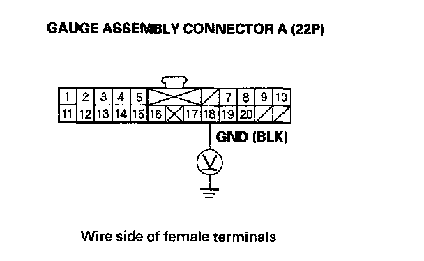
6. Measure the voltage between the gauge assembly connector A (22P) terminal No. 18 and body ground.
Is there less then 0.1 V?
YES - Do the self-diagnostic function troubleshooting for the gauge assembly.
NO - Repair open in the wire between the gauge assembly and body ground (G501).
7. Turn the ignition switch OFF.
8. Disconnect the VSA modulator-control unit 47P connector.
9. Turn the ignition switch ON (II).
Does the ABS indicator come on?
YES - Check for loose terminals in the VSA modulator-control unit 47P connector. If necessary, substitute a known-good VSA modulator-control unit, and recheck.
NO - Go to step 10.
10. Turn the ignition switch OFF.
11. Check the ABS indicator bulb in the gauge assembly.
Is the bulb OK?
YES - Go to step 12.
NO - Replace the ABS indicator bulb.
12. Disconnect the gauge assembly connector B (30P).
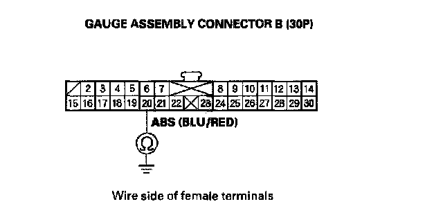
13. Check for continuity between the gauge assembly connector B (30P) terminal No. 20 and body ground.
Is there continuity?
YES - Repair short to body ground in the wire between the gauge assembly and the VSA modulator-control unit.
NO - Check for loose terminals in the VSA modulator-control unit 47P connector. If necessary, substitute a known-good VSA modulator-control unit, and retest.