Air Injection Hose/Tube: Service and Repair
Secondary Air Injection (AIR) Control Valve to Exhaust Manifold Tube
Special Service Tools

Engine lifting brackets
303-749

Engine support bracket
303-021
Removal
1 Remove the cover and disconnect the battery ground cable. For additional information, refer to Specifications [1][2]Battery
2
WARNING: Do not work on or under a vehicle supported only by a jack. Always support the vehicle on safety stands.
Raise and support the vehicle.
3 Drain the coolant. For additional information, refer to Cooling System Draining, Filling and Bleeding - Vehicles With: Supercharger Cooling System Draining, Filling and Bleeding
4 Remove the hood. For additional information, refer to Hood Service and Repair
5 Remove the front wheels and tires. For additional information, refer to Wheel and Tire Service and Repair
6 Remove the intake air resonator. For additional information, refer to Intake Air Resonator Service and Repair
7 Remove the engine undershield. For additional information, refer to Air Deflector Service and Repair
8 Remove the coolant expansion tank. For additional information, refer to Coolant Expansion Tank Service and Repair
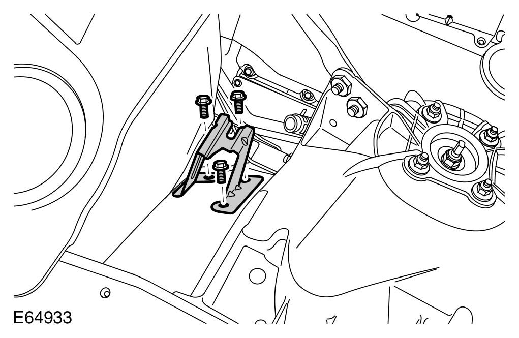
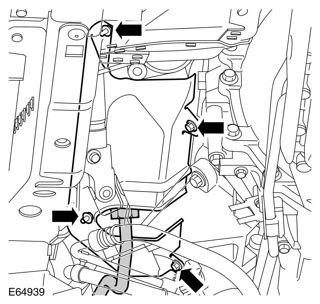
9 Remove the coolant expansion tank support bracket.
- Remove the 3 nuts.
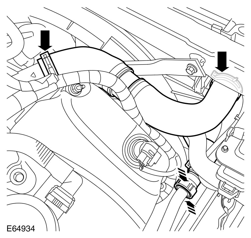
10 Remove the radiator top hose.
- Release the 2 clips.
- Disconnect the quick release connector.
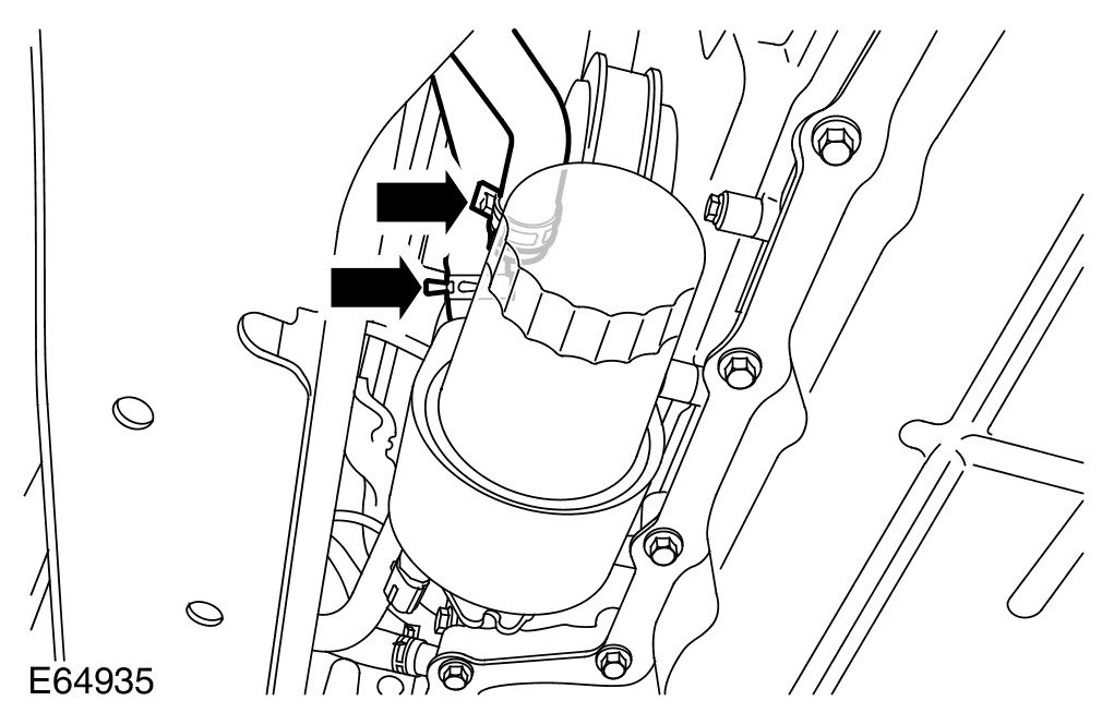
11 Disconnect the coolant hoses from the engine oil cooler.
- Release the 2 clips.
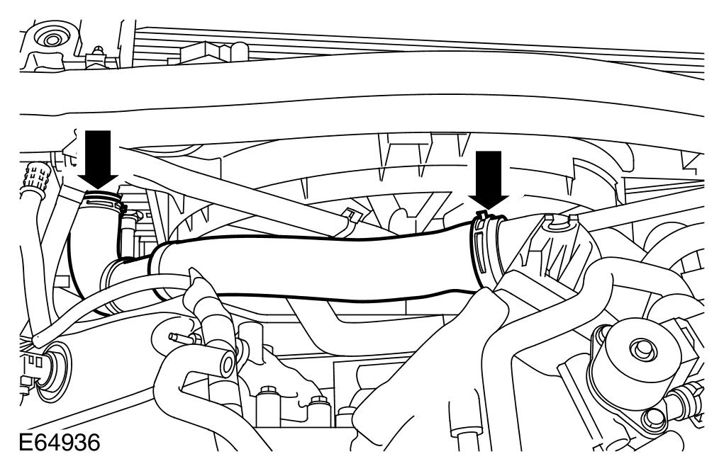
12 Remove the radiator bottom hose.
- Release the 2 clips.
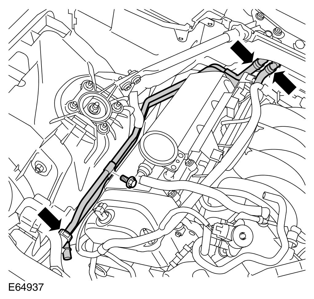
13 Remove the coolant rail.
- Remove the bolt.
- Disconnect the 3 quick release connectors.

14
CAUTION: Protect the paintwork during this operation.
Using the special tools, support the engine.

15
NOTE:
RH illustration shown, LH is similar
Release the engine mounts.
- Remove and discard the 2 nuts.
- Raise the engine.
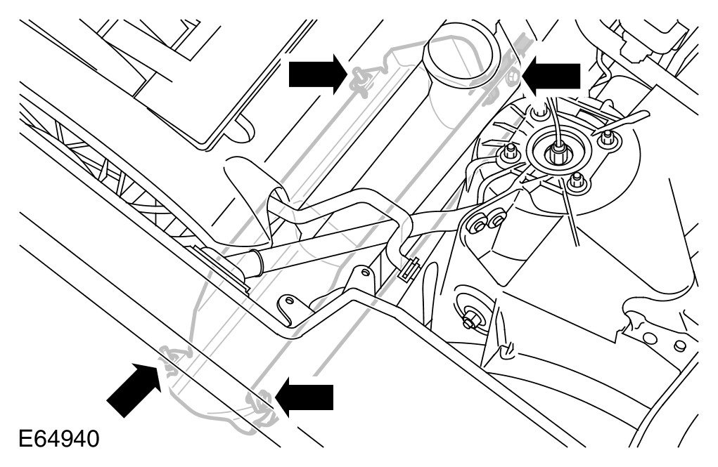
16 Release the RH exhaust manifold heat shield.
- Remove the 4 screws.
17 Release the AIR tube from the RH exhaust manifold.
18 Release the LH exhaust manifold heat shield.
- Remove the 4 screws.
19 Release the AIR tube from the LH exhaust manifold.
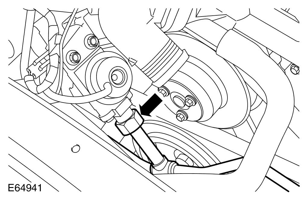
20 Release the AIR tube from the AIR control valve.
21 Remove the AIR tube.
Installation
1 Install the AIR tube.
2 Attach the AIR tube to the exhaust manifolds.
- Tighten the unions to 35 Nm (26 lb.ft).
3 Attach the AIR tube to the AIR control valve.
- Tighten the union to 35 Nm (26 lb.ft).
4 Install the LH exhaust manifold heat shield.
- Tighten the screws.
5 Install the RH exhaust manifold heat shield.
- Tighten the screws.
6 Lower the engine onto its mounts.
- Tighten the new nuts to 63 Nm (46 lb.ft).
- Remove the special tools.
7 Install the coolant rail.
- Tighten the bolt to 10 Nm (7 lb.ft).
- Connect the quick release connectors.
8 Install the radiator bottom hose.
- Secure with the clips.
9 Install the radiator top hose.
- Secure with the clips.
- Connect the quick release connector.
10 Connect the engine oil cooler, coolant hoses.
- Secure with the clips.
11 Install the coolant expansion tank support bracket.
- Tighten the nuts to 10 Nm (7 lb.ft).
12 Install the coolant expansion tank. For additional information, refer to Coolant Expansion Tank Service and Repair
13 Install the engine undershield. For additional information, refer to Air Deflector Service and Repair
14 Install the intake air resonator. For additional information, refer to Intake Air Resonator Service and Repair
15 Install the front wheels and tires. For additional information, refer to Wheel and Tire Service and Repair
16 Install the hood. For additional information, refer to Hood Service and Repair
17 Connect the battery ground cable and install the cover. For additional information, refer to Specifications [1][2]Battery
18 Top-up and bleed the coolant. For additional information, refer to Cooling System Draining, Filling and Bleeding - Vehicles With: Supercharger Cooling System Draining, Filling and Bleeding