Installation
INSTRUMENT PANEL: INSTRUMENT PANEL SAFETY PAD: INSTALLATION
1. INSTALL INSTRUMENT PANEL STAY
(a) Engage the claw to install the instrument panel stay.

2. INSTALL INSTRUMENT PANEL CLIP
(a) Engage the 4 claws to install the 4 instrument panel clips.

3. INSTALL INSTRUMENT PANEL SAFETY PAD ASSEMBLY
(a) Engage the 5 claws.
NOTICE:
Do not allow the wire harness to get caught in the claws.
(b) Engage the 2 clamps.
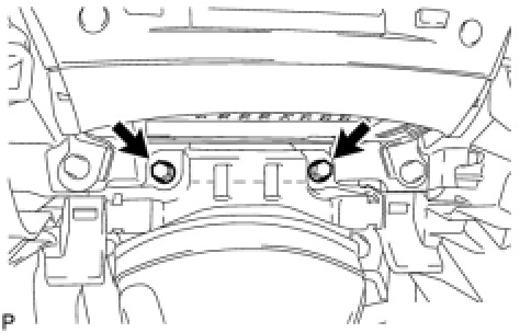
(c) Install the 2 passenger airbag bolts [A] or [B].
Torque : 20 Nm (204 kgf-cm, 15 ft-lbf)
(d) Install the 6 bolts [D] and nut [H].

(e) Engage the 2 claws to install the cooler thermistor.
(f) Engage the clamps.
(g) Connect the connectors to install the instrument panel safety pad assembly.

4. CONNECT PASSENGER AIRBAG CONNECTOR Installation
5. INSTALL NO. 1 CONSOLE BOX DUCT
(a) Install the No. 1 console box duct with the clip.

6. INSTALL NO. 2 CONSOLE BOX DUCT (for Manual Transmission)
(a) Install the No. 2 console box duct with the clip.

7. INSTALL NO. 2 CONSOLE BOX DUCT (for Automatic Transmission)
(a) Install the No. 2 console box duct with the 2 clips.

8. INSTALL FRONT STEREO COMPONENT SPEAKER ASSEMBLY (w/ Front Center Speaker) Installation
9. INSTALL NO. 3 INSTRUMENT PANEL SPEAKER PANEL SUB-ASSEMBLY
(a) Engage the 7 claws and 2 clips to install the No. 3 instrument panel speaker panel sub-assembly.

10. INSTALL NO. 2 INSTRUMENT PANEL REGISTER ASSEMBLY
(a) Connect the connector.

(b) Engage the 4 claws and 2 clips to install the No. 2 instrument panel register assembly.
11. INSTALL NO. 1 INSTRUMENT PANEL REGISTER ASSEMBLY
(a) Connect the connector.

(b) Engage the 7 claws and 2 clips to install the No. 1 instrument panel register assembly.
12. INSTALL FRONT PILLAR GARNISH LH Installation
13. INSTALL FRONT PILLAR GARNISH RH
HINT
Use the same procedure for the RH side and LH side.
14. INSTALL POWER SOURCE CONTROL ECU
(a) Install the power source control ECU with the bolt and 2 nuts.

Bolt - Torque : 11 Nm (107 kgf-cm, 8 ft-lbf)
Nut - Torque : 13 Nm (126 kgf-cm, 9 ft-lbf)
(b) Connect the connector.
15. INSTALL GLOVE COMPARTMENT DOOR ASSEMBLY
(a) Connect the connectors.

(b) Engage the 2 claws.
(c) Install the glove compartment door assembly with the 5 screws [E].
16. INSTALL FRONT PASSENGER SIDE KNEE AIRBAG ASSEMBLY Installation
17. INSTALL NO. 2 INSTRUMENT PANEL UNDER COVER SUB-ASSEMBLY
(a) Engage the 4 clips to install the No. 2 instrument panel under cover sub-assembly.

18. INSTALL SIDE INSTRUMENT PANEL RH
(a) Engage the 5 claws and 3 clips to install the side instrument panel RH.

19. INSTALL FRONT DOOR OPENING TRIM COVER RH
(a) Engage the 6 claws to install the front door opening trim cover RH.

20. INSTALL FRONT DOOR SCUFF PLATE RH (w/o Illumination)
HINT
Use the same procedure for the RH side and LH side.
21. INSTALL FRONT DOOR SCUFF PLATE RH (w/ Illumination)
HINT
Use the same procedure for the RH side and LH side.
22. INSTALL COMBINATION METER ASSEMBLY
(a) Connect the connectors.

(b) Engage the 2 pins.
(c) Engage the 2 claws to install the combination meter assembly.
23. INSTALL INSTRUMENT CLUSTER FINISH PANEL SUB-ASSEMBLY
(a) Install the instrument cluster finish panel sub-assembly with the 2 screws [G] and 2 clips.

24. INSTALL DRIVER SIDE KNEE AIRBAG ASSEMBLY Installation
25. INSTALL LOWER INSTRUMENT PANEL FINISH PANEL SUB-ASSEMBLY
(a) Connect the connectors.

(b) Engage the 7 clips to install the lower instrument panel finish panel sub-assembly.
26. INSTALL NO. 1 INSTRUMENT PANEL UNDER COVER SUB-ASSEMBLY
(a) Connect the connectors.

(b) Insert the No. 1 instrument panel under cover sub-assembly into the guide as shown in the illustration.
(c) Engage the 2 claws.
(d) Install the No. 1 instrument panel under cover sub-assembly with the 2 screws [E].
27. INSTALL SIDE INSTRUMENT PANEL LH
(a) Engage the 5 claws and 3 clips to install the side instrument panel LH.

28. INSTALL FRONT DOOR OPENING TRIM COVER LH
(a) Engage the 6 claws to install the front door opening trim cover LH.

29. INSTALL FRONT DOOR SCUFF PLATE LH (w/o Illumination) Installation
30. INSTALL FRONT DOOR SCUFF PLATE LH (w/ Illumination) Installation
31. INSTALL TURN SIGNAL SWITCH ASSEMBLY WITH SPIRAL CABLE SUB-ASSEMBLY Installation
32. INSTALL STEERING COLUMN COVER (for Manual Tilt and Manual Telescopic Steering Column) Installation
33. INSTALL STEERING COLUMN COVER (for Power Tilt and Power Telescopic Steering Column) Installation
34. ADJUST SPIRAL CABLE SUB-ASSEMBLY Installation
35. INSTALL STEERING WHEEL ASSEMBLY Installation
36. INSTALL STEERING PAD Installation
37. INSTALL LOWER NO. 3 STEERING WHEEL COVER Installation
38. INSTALL LOWER NO. 2 STEERING WHEEL COVER Installation
39. INSTALL INTEGRATION CONTROL PANEL WITH RADIO RECEIVER ASSEMBLY (w/o Navigation System) Installation
40. INSTALL DISPLAY AND NAVIGATION MODULE DISPLAY WITH RADIO RECEIVER ASSEMBLY (w/ Navigation System) Installation
41. INSTALL CENTER LOWER INSTRUMENT CLUSTER FINISH PANEL
(a) Engage the 4 claws to install the center lower instrument cluster finish panel.

42. INSTALL NO. 3 INSTRUMENT PANEL REGISTER ASSEMBLY
(a) Connect the connector.

(b) Engage the 11 claws to install the No. 3 instrument panel register assembly.

43. INSTALL CONSOLE BOX
(a) Engage the 2 claws and 2 clips.

(b) Connect each connector.
(c) Install the 2 bolts [C].
(d) Install the 2 bolts [C].

(e) Connect the 2 connectors.

(f) Engage the 2 clamps.
(g) Install the 2 bolts [C].
44. INSTALL CONSOLE BOX REGISTER ASSEMBLY
(a) Engage the 2 claws and 4 clips to install the console box register assembly.

(b) Install the rear ash receptacle assembly.
45. INSTALL FRONT ASH RECEPTACLE ASSEMBLY
(a) Connect the connectors.

(b) Insert the protruding parts of the front ash receptacle assembly into the 2 guide holes as shown in the illustration.
(c) Install the front ash receptacle assembly with the 2 screws [F].

46. INSTALL FRONT CONSOLE PANEL SUB-ASSEMBLY (for Manual Transmission)
(a) Engage the 6 clips.

(b) Close the snap.

47. INSTALL REAR CONSOLE PANEL SUB-ASSEMBLY (for Manual Transmission)
(a) w/ Seat Heater System:
(1) Connect the connector.
(b) Engage the 7 claws and 2 clips to install the rear console panel sub-assembly.

48. INSTALL CONSOLE PANEL SUB-ASSEMBLY (for Automatic Transmission)
(a) Connect the connectors.

(b) Engage the 8 clips to install the console panel sub-assembly.
49. INSTALL UPPER NO. 2 CONSOLE PANEL GARNISH (for Automatic Transmission)
(a) Engage the claw and 2 clips to install the upper No. 2 console panel garnish.

50. INSTALL UPPER NO. 1 CONSOLE PANEL GARNISH (for Automatic Transmission)
(a) Engage the claw and 2 clips to install the upper No. 1 console panel garnish.

51. INSTALL SHIFT LEVER KNOB SUB-ASSEMBLY (for Manual Transmission)
(a) Turn the shift lever knob clockwise and install the shift lever knob sub-assembly.

52. INSTALL SHIFT LEVER KNOB SUB-ASSEMBLY (for Automatic Transmission)
(a) Turn the shift lever knob clockwise and install the shift lever knob sub-assembly.

53. CONNECT CABLE TO NEGATIVE BATTERY TERMINAL
54. INSPECT STEERING PAD Installation
55. INSPECT SRS WARNING LIGHT
Diagnosis System