Installation
4GR-FSE FUEL: FUEL INJECTOR: INSTALLATION
1. INSTALL FUEL INJECTOR SEAL
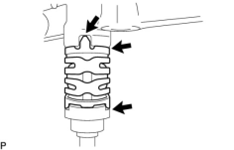
(a) Apply engine conditioner to the injector area shown in the illustration. Using a piece of cloth, clean carbon deposits from the injector and its grooves.
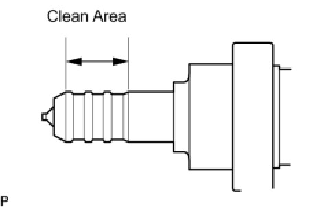
NOTICE:
* Do not clean the tip of the injector.
* Do not use a wire brush to clean the injector.
* If an injector is dropped or the tips of the injectors are struck, replace it with a new one.
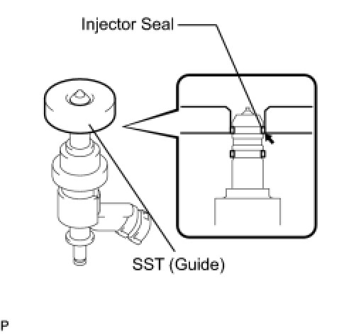
(b) Apply engine oil to the injector contact surface of SST (guide). Then attach SST (guide) to the injector with the tapered inner portion facing the tip of the injector, as shown in the illustration.
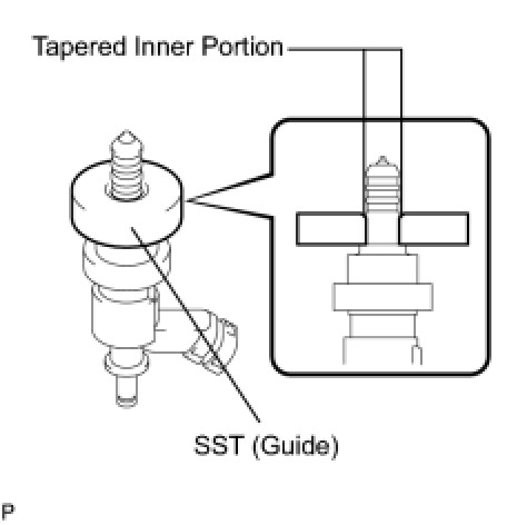
SST : 09260-39015
09268-03020
(c) Install a new injector seal to SST (holder).
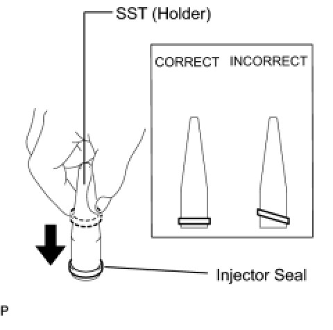
SST : 09260-39015
09268-03010
NOTICE:
Be careful not to install the injector seal to SST (holder) at an angle. Doing so will stretch the seal and correcting this problem is very complicated.
(d) Install SST (holder with injector seal) to the tip of the injector. Slide the seal downward into the injector groove (injector connector side) with your fingers, as shown in the illustration.
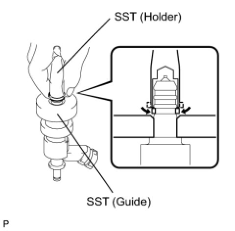
SST : 09260-39015
09268-03010
09268-03020
HINT
Check that the seal covers the circumference of the injector groove as shown in the illustration.
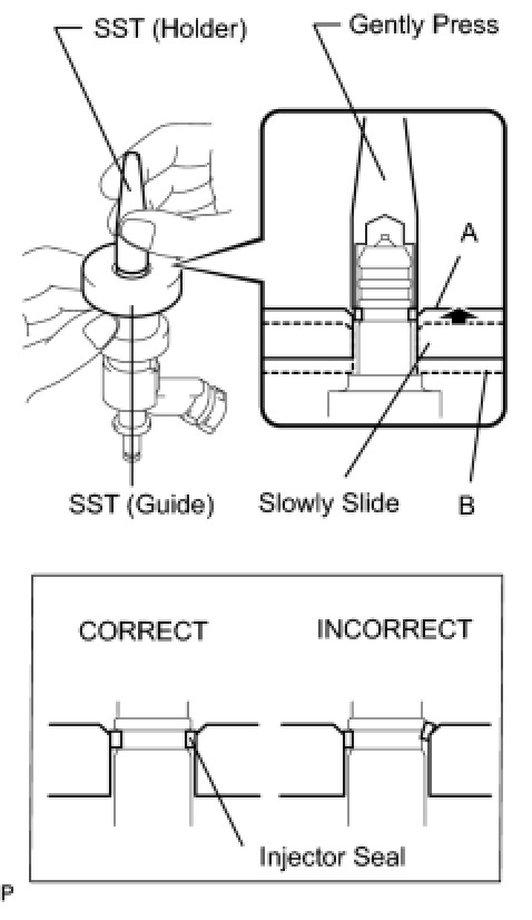
(e) Using SST (holder), gently press downward on the injector seal (injector connector side). Then slowly slide SST (guide) towards the injector tip to settle the seal into the injector groove.
SST : 09260-39015
09268-03010
09268-03020
NOTICE:
Be careful that the seal is not pinched between SST (guide) and the injector groove. Replace the seal if it becomes damaged.
HINT
* When using SST (guide) to settle the seal into the groove, SST (guide) only needs to be slid upward to the position labeled A in the illustration.
* After using SST (guide) to settle the seal into the groove, return SST (guide) to its position labeled B in the illustration.
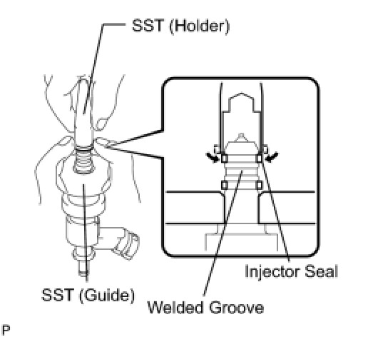
(f) Install a new injector seal to the injector groove (injector tip side) as shown in the illustration.
SST : 09260-39015
09268-03010
09268-03020
(g) Check that the seal covers the circumference of the injector groove as shown in the illustration.
SST : 09260-39015
09268-03010
09268-03020
NOTICE:
Make sure that the seal does not slip into the welded groove of the injector shown in the illustration. If it does, replace it with a new one.
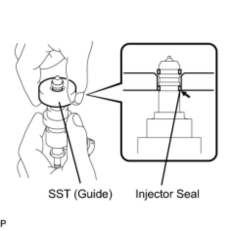
(h) Slowly slide SST (guide) towards the tip of the injector. When the injector contact surface of SST (guide) aligns with the seal (injector connector side) as shown in the illustration, hold the position for 5 seconds or more to fully align the seal into the injector groove.
SST : 09260-39015
09268-03020
NOTICE:
Be careful that the seal is not pinched between SST (guide) and the injector groove. Replace the seal if it becomes damaged.
HINT
* Set SST (guide) so that its bottom surface and seal are flush.
* If there is difficulty in sliding SST upward, slowly wiggle it from side to side while sliding it up the injector little by little.
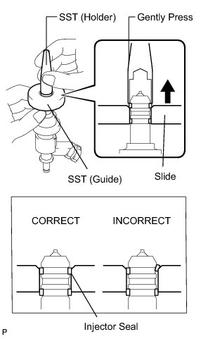
(i) Using SST (holder), gently press downward on the injector seal (injector tip side). Then slowly slide SST (guide) towards the injector tip to settle the seal into the injector groove.
SST : 09260-39015
09268-03010
09268-03020
NOTICE:
Be careful that the seal is not pinched between SST (guide) and the injector groove. Replace the seal if it becomes damaged.
(j) Slowly slide SST (guide) towards the tip of the injector. When the injector contact surface of SST (guide) aligns with the seal (injector tip side) as shown in the illustration, hold the position for 5 seconds or more to fully align the seal into the injector groove.
SST : 09260-39015
09268-03020
NOTICE:
Be careful that the seal is not pinched between SST (guide) and the injector groove. Replace the seal if it becomes damaged.
HINT
* Set SST (guide) so that its bottom surface and the seal's bottom surface are flush.
* If there is difficulty in sliding SST upward, slowly wiggle it from side to side while sliding it up the injector little by little.
(k) After installing the seals, check that the seal is not scratched, deformed or protruding from the injector groove.
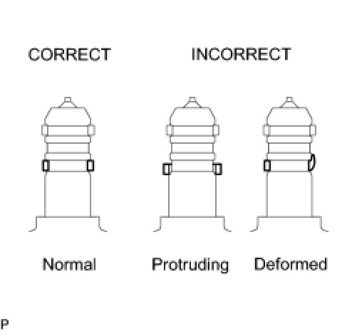
NOTICE:
If the seal is scratched, deformed or protruding from the groove, replace it with a new one.
2. INSTALL FUEL INJECTOR
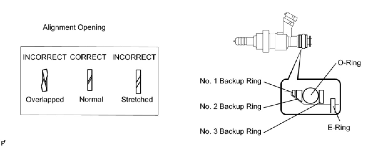
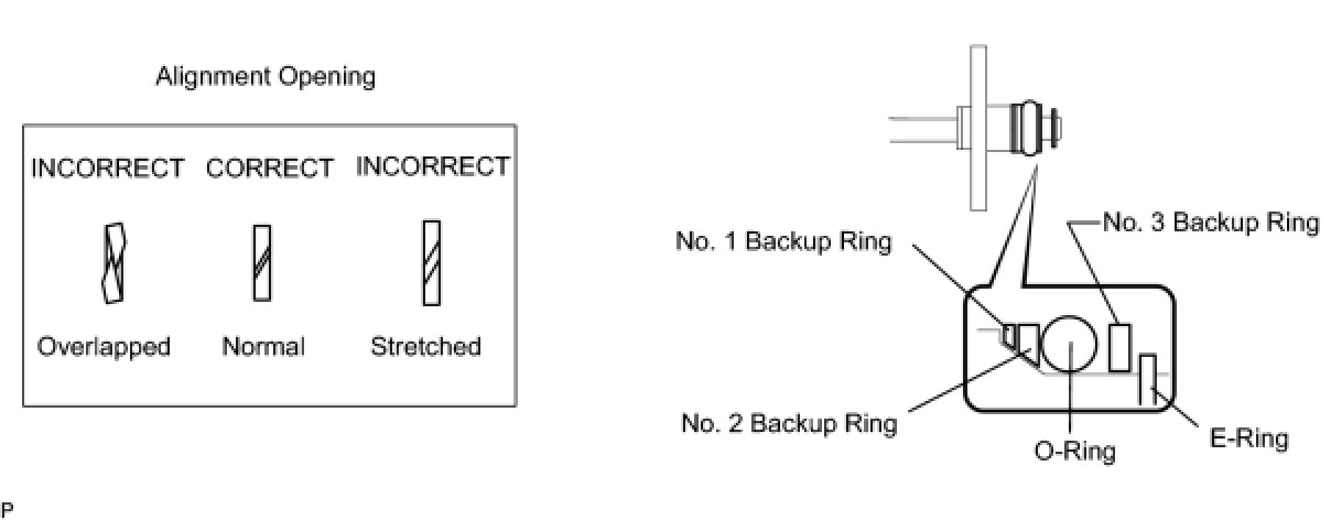
(a) Install a new O-ring, new backup rings (No. 1, No. 2, No. 3) and new E-ring to the fuel injector as shown in the illustration.
NOTICE:
* Check that there is no foreign matter or damaged areas in the injector's O-ring groove.
* Check that the No. 1 and No. 2 backup rings are installed in the correct direction.
* Make sure that the backup rings and O-ring are installed in the correct order.
* Check that the alignment openings of the backup rings are not overlapped or stretched as shown in the illustration.
* After installing the O-ring, check that it is not contaminated with foreign matter and is not damaged.
(b) Install the injector nozzle holder clamp.
(c) Apply gasoline to the O-ring. Install the nozzle holder clamp by aligning the protruding part of the clamp to the notch of the delivery pipe.
NOTICE:
* Make sure that there is no gap between the delivery pipe and clamp.
* Check that there is no foreign matter or damage to the injector insertion hole of the delivery pipe.
* Insert the injector straight into the delivery pipe without tilting it.
3. INSTALL NO. 1 FUEL DELIVERY PIPE
(a) Install a new injector vibration insulator to the cylinder head.
(b) Apply lubricant to the installation hole of the injector.
(c) Insert the stud bolt into the fuel delivery pipe until the screw threads protrude enough so that a nut can be attached.
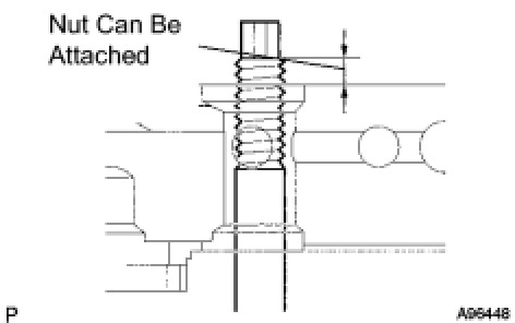
NOTICE:
* If an injector is dropped or the tips of the injectors are struck, replace it with a new one.
* Check that there is no foreign matter or damage to the injector insertion hole of the delivery pipe.
* When inserting the fuel delivery pipe, push it in evenly without tilting it.
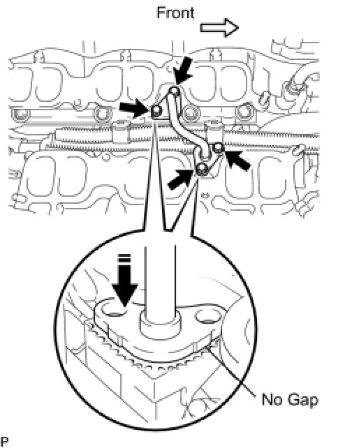
(d) Install the fuel delivery pipe by uniformly tightening the 2 bolts and 2 nuts in several passes in the order shown in the illustration.
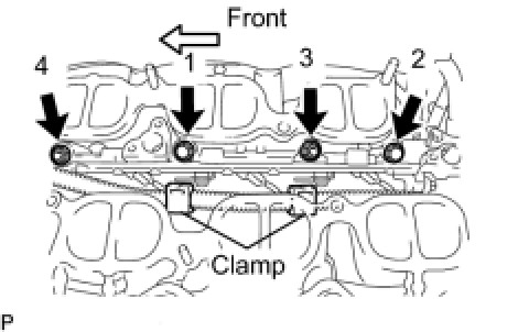
Torque : 26 Nm (265 kgf-cm, 19 ft-lbf)
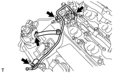
(e) Connect the 3 connectors and 2 clamps.
4. INSTALL NO. 2 FUEL DELIVERY PIPE
(a) Install new injector vibration insulators to the cylinder head.
(b) Apply lubricant to the installation holes of the injectors.
(c) Insert the stud bolt into the delivery pipe until the screw threads protrude enough so that a nut can be attached.
NOTICE:
* If an injector is dropped or the tips of the injectors are struck, replace it with a new one.
* Check that there is no foreign matter or damage to the injector insertion hole of the delivery pipe.
* When inserting the fuel delivery pipe, push it in evenly without tilting it.
(d) Install the fuel delivery pipe by uniformly tightening the 2 bolts and 2 nuts in several passes in the order shown in the illustration.
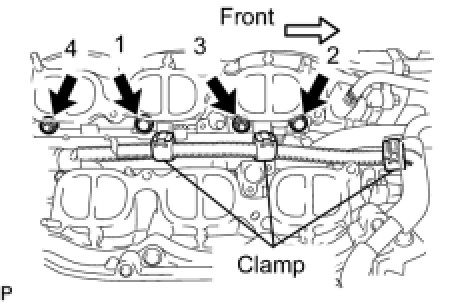
Torque : 26 Nm (265 kgf-cm, 19 ft-lbf)
(e) Connect the 3 connectors and 3 clamps.
5. INSTALL NO. 3 FUEL PIPE
(a) Install a new O-ring, new backup rings (No. 1, No. 2) and new E-ring to the fuel injector as shown in the illustration.
NOTICE:
* Check that there is no foreign matter or damaged areas in the injector's O-ring groove.
* Check that the No. 1 and No. 2 backup rings are installed in the correct direction.
* Make sure that the backup rings and O-ring are installed in the correct order.
* Check that the alignment openings of the backup rings are not overlapped or stretched as shown in the illustration.
* After installing the O-ring, check that it is not contaminated with foreign matter and is not damaged.
* Check that the fuel pipe installation end is not contaminated with foreign matter and is not damaged.
(b) Apply gasoline to the O-ring.
(c) Press the fuel pipe and delivery pipe together by hand until there is no gap between them. Then install the No. 3 fuel pipe with the 4 bolts.
Torque : 10 Nm (102 kgf-cm, 7 ft-lbf)
NOTICE:
Do not install the No.3 fuel pipe at an angle.
6. INSTALL NO. 2 FUEL PIPE
(a) Install a new O-ring, new backup rings (No. 1 and No. 2) and new E-ring to the fuel injector as shown in the illustration.
NOTICE:
* Check that there is no foreign matter or damaged areas in the injector's O-ring groove.
* Check that the No. 1 and No. 2 backup rings are installed in the correct direction.
* Make sure that the backup rings and O-ring are installed in the correct order.
* Check that the alignment openings of the backup rings are not overlapped or stretched as shown in the illustration.
* After installing the O-ring, check that it is not contaminated with foreign matter and is not damaged.
* Check that the No. 3 fuel pipe installation end is not contaminated with foreign matter and is not damaged.
(b) Apply gasoline to the O-ring and connect the fuel pipe to the delivery pipe.
NOTICE:
* Do not install the No.2 fuel pipe at an angle.
* Do not install the bolt at this time.
7. INSTALL FUEL PUMP ASSEMBLY Installation
8. CONNECT NO. 2 FUEL PIPE Installation
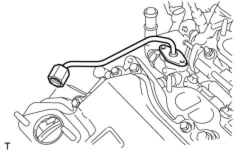
9. INSTALL NO. 1 FUEL PIPE
(a) Install the fuel pipe with the 2 bolts.
Torque : 10 Nm (102 kgf-cm, 7 ft-lbf)
(b) Connect the 2 fuel hoses.
10. INSTALL FUEL PRESSURE PULSATION DAMPER Installation
11. CONNECT WATER HOSE JOINT
(a) Connect the water hose joint with the bolt.

Torque : 10 Nm (102 kgf-cm, 7 ft-lbf)
12. INSTALL INTAKE MANIFOLD
(a) Install a new gasket and the intake manifold with the 4 bolts and 4 nuts.

Torque : 21 Nm (214 kgf-cm, 15 ft-lbf)
(b) Connect the SCV position sensor connector.
(c) Connect the DC motor connector for the SCV.
13. INSTALL INTAKE AIR SURGE TANK
(a) Install a new gasket to the intake air surge tank.

(b) Using a 5 mm hexagon socket wrench, install the 6 bolts.
Bolts except A - Torque : 18 Nm (184 kgf-cm, 13 ft-lbf)
(c) Install the bolt and 2 nuts to the intake air surge tank.
Bolt A - Torque : 21 Nm (214 kgf-cm, 15 ft-lbf)
Nut - Torque : 16 Nm (163 kgf-cm, 12 ft-lbf)
(d) Install the surge tank stay to the intake air surge tank.

Torque : 21 Nm (214 kgf-cm, 15 ft-lbf)
(e) Connect the water hose joint with the bolt.

Torque : 10 Nm (102 kgf-cm, 7 ft-lbf)
(f) Connect the ventilation hose to the intake air surge tank.

(g) Connect the wire harness and hose to the intake air surge tank.
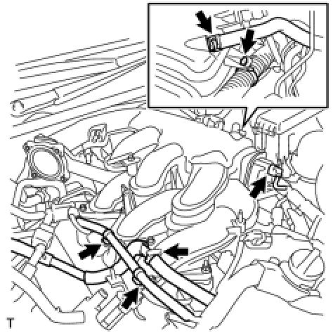
(h) Connect the purge VSV to the intake air surge tank.
Torque : 18 Nm (184 kgf-cm, 13 ft-lbf)
(i) Connect the vacuum hose to the intake air surge tank.
14. INSTALL COLD START INJECTOR
(a) Connect the cold start injector with the 2 bolts.

Torque : 10 Nm (102 kgf-cm, 7 ft-lbf)
(b) Connect the cold cold start injector connector.
15. INSTALL THROTTLE WITH MOTOR BODY ASSEMBLY Installation
16. INSTALL AIR CLEANER CAP WITH AIR CLEANER HOSE Installation
17. CONNECT NO. 2 VENTILATION HOSE Installation
18. CONNECT CABLE TO NEGATIVE BATTERY TERMINAL Installation
19. ADD ENGINE COOLANT Testing and Inspection
20. INSPECT FOR COOLANT LEAK Testing and Inspection
21. INSPECT FOR FUEL LEAK Testing and Inspection
22. INSTALL COWL TOP VENTILATOR LOUVER SUB-ASSEMBLY Installation
23. INSTALL FRONT WIPER ARM AND BLADE ASSEMBLY LH Installation
24. INSTALL FRONT WIPER ARM AND BLADE ASSEMBLY RH Installation
25. INSTALL FRONT WIPER ARM HEAD CAP Installation
26. INSTALL ROOF DRIP SIDE FINISH MOULDING LH
27. INSTALL ROOF DRIP SIDE FINISH MOULDING RH
28. INSTALL FRONT UPPER FENDER PROTECTOR LH Installation
29. INSTALL FRONT UPPER FENDER PROTECTOR RH
HINT
Installation procedure of the RH side is the same as that of the LH side.
30. INSTALL V-BANK COVER SUB-ASSEMBLY Installation
31. INSTALL ENGINE ROOM SIDE COVER LH Installation
32. INSTALL ENGINE ROOM SIDE COVER RH Installation
33. INSTALL COOL AIR INTAKE DUCT SEAL Installation
34. CHECK FUNCTION OF THROTTLE WITH MOTOR BODY ASSEMBLY On-Vehicle Inspection