TC Terminal Circuit
NAVIGATION / MULTI INFO DISPLAY: NAVIGATION SYSTEM (for HDD): TC Terminal Circuit
- TC Terminal Circuit
DESCRIPTION
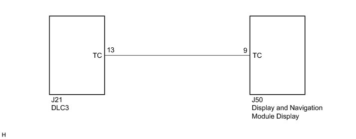
The display and navigation module display is connected to the DLC3 by the vehicle wire harness.
HINT
If there is a short circuit to ground in the wire between the display and navigation module display and DLC3, the diagnosis mode screen will be displayed on the multi-display immediately after the engine switch is turned on (ACC).
WIRING DIAGRAM
INSPECTION PROCEDURE
PROCEDURE
1. CHECK HARNESS AND CONNECTOR
(a) Disconnect the J50 display and navigation module display connector.
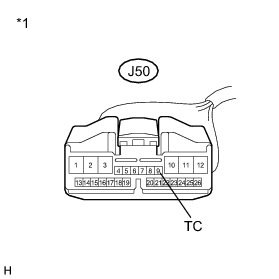
(b) Measure the resistance according to the value(s) in the table below.
Standard Resistance:

Text in Illustration

NG -- REPAIR OR REPLACE HARNESS OR CONNECTOR
OK -- PROCEED TO NEXT SUSPECTED AREA SHOWN IN PROBLEM SYMPTOMS TABLE Problem Symptoms Table