Test J
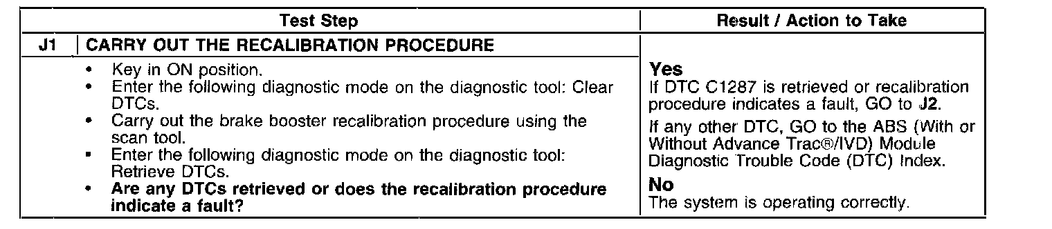
Test J1:
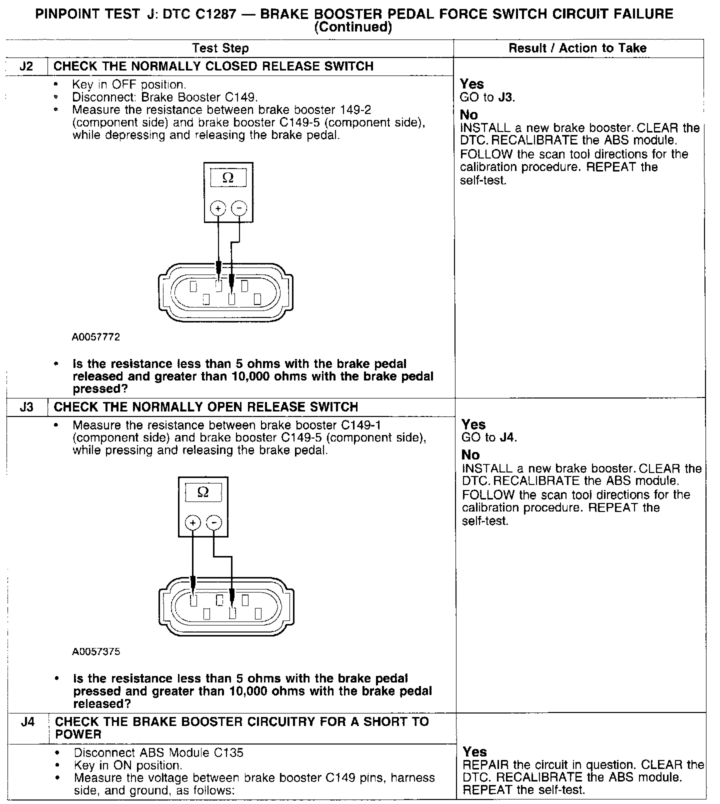
Test J2-J4:
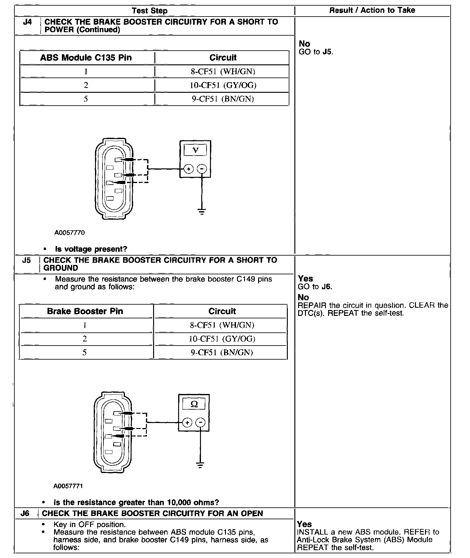
Test J4-J6:
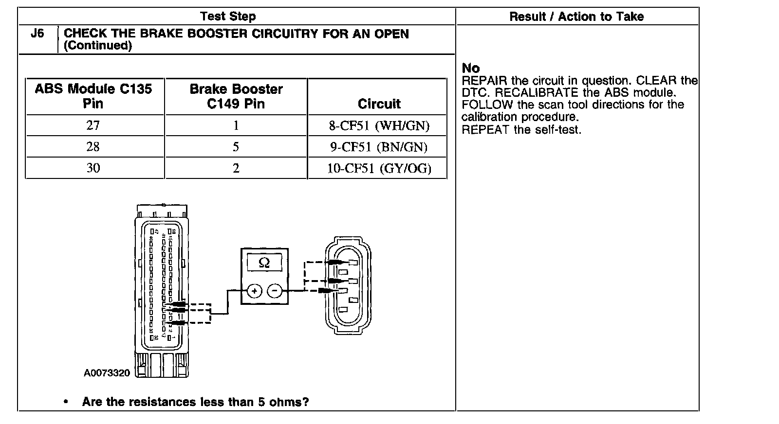
Test J6 Continued:
PINPOINT TEST J: DTC C1287-BRAKE BOOSTER PEDAL FORCE SWITCH CIRCUIT FAILURE
CAUTION: Use the Flex Probe Kit for all test connections to prevent damage to the wiring terminals. Do not use standard multimeter probes.
Normal Operation
The active brake booster has a normally open (NO), and a normally closed, (NC) pedal force switch that operates according to driver brake applications.
The NO pedal force switch circuit is 8-CF51 (WH/GN). The NC pedal force switch circuit is 10-CF5 1 (GY/OG).
Possible Causes
^ NO pedal force switch circuit 8-CF51 (WH/GN).
^ NC pedal force Switch]1 circuit 10-CF51 (GY/OG).
^ Active brake booster.
^ ABS module.