Fuel Evaporation System Test
Test Condition:
- Engine idling and coolant temperature above 50°C (122°F)
Functional Diagram of Vacuum Line Routing
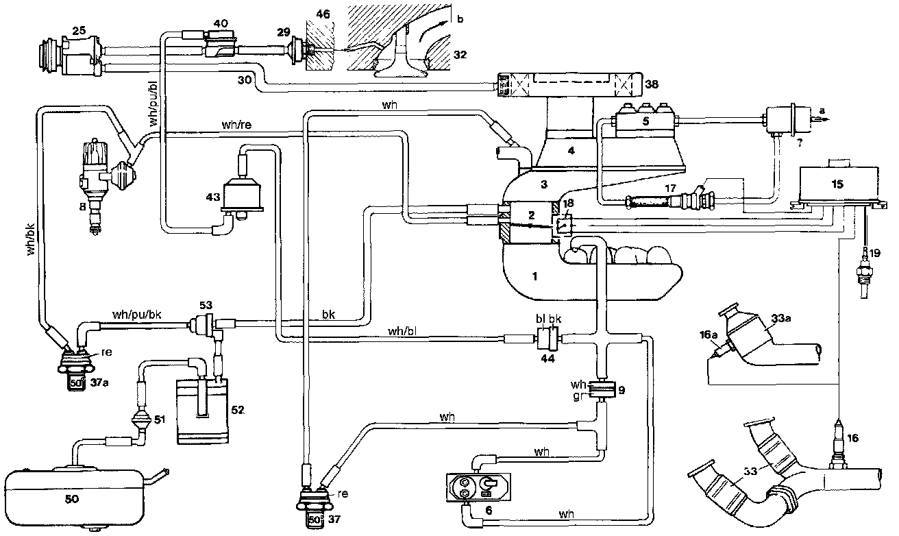
1. Intake manifold
2. Throttle valve housing
3. Air guide housing
4. Air flow sensor
5. Fuel distributor
6. Warm-up compensator
7. Pressure damper
8. Ignition distributor
9. Orifice
15. Lambda control unit
16. Oxygen sensor (model 107)
16a. Oxygen sensor (model 126)
17. Frequency valve
18. Throttle valve switch
19. Temperature switch 16°C (61°F) oil
25. Air pump
29. Check valve (air injection)
30. Suction line, air pump
32. Cylinder head
33. Primary catalyst (model 107)
33a. Primary catalyst (model 126)
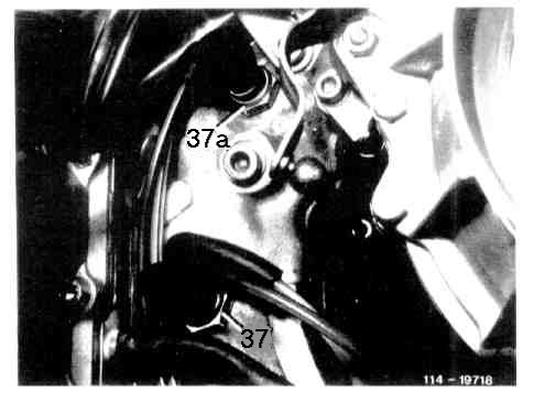
37. Thermo-vacuum valve 50°C (122°F)
37a. Thermo-vacuum valve 50° (122°F)
38. Air cleaner
40. Air injection shutoff valve
43. Switchover valve
44. Check valve (vacuum)
46. Timing chain housing cover
50. Fuel tank
51. Vent valve
52. Charcoal canister
53. Purge valve
a) Leak-off connection
b) To exhaust manifold
Color Code
bk = black
bl = blue
gr = green
pu = purple
re = red
wh = white
Test Procedure:
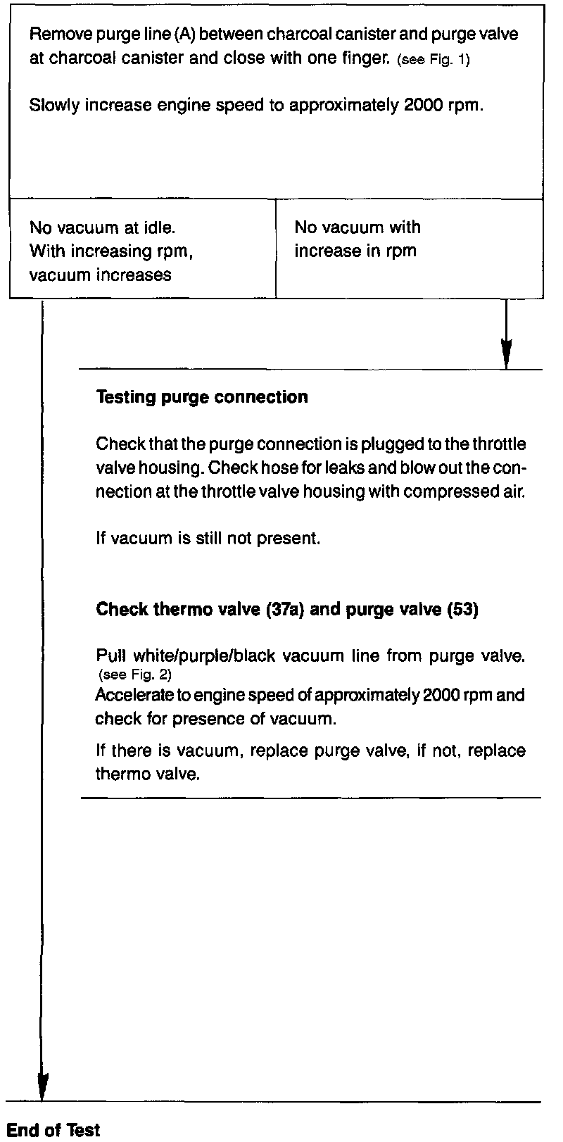
Fig. 1:
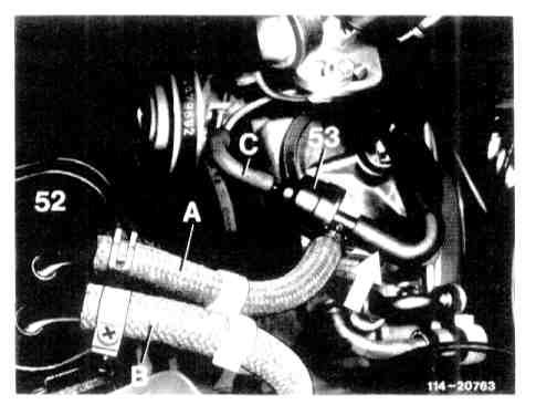
Fig. 2: