Pinpoint Test B: DTC P0645
Climate Control System
Pinpoint Tests
Pinpoint Test B: DTC P0645
Refer to Wiring Diagram Set 54, Manual Climate Control System for schematic and connector information. Diagrams By Number
Refer to Wiring Diagram Set 55, Automatic Climate Control System for schematic and connector information. Diagrams By Number
Normal Operation
Under normal operation, voltage is provided to the A/C clutch relay coil through circuit CBB40 (YE/GN). When A/C is requested, and A/C line pressures allow, a ground is provided to the A/C clutch relay coil from the PCM through circuit CH302 (WH/BN), energizing the A/C clutch relay.
- DTC P0645 - A/C Clutch Relay Control Circuit - The DTC sets when the PCM grounds the relay circuit, excessive current draw is detected on the relay circuit or, with the relay circuit not grounded by the PCM, voltage is not detected on the relay circuit the PCM expects to detect voltage coming through the relay coil to the relay circuit.
This pinpoint test is intended to diagnose the following:
- Wiring, terminals or connectors
- A/C clutch relay
- PCM
PINPOINT TEST B: DTC P0645
-------------------------------------------------
B1 CHECK THE VOLTAGE TO THE A/C CLUTCH RELAY
- Ignition OFF.
- Disconnect: A/C Clutch Relay.
- Ignition ON.
- Measure the voltage between ground and the A/C clutch relay socket pin 2, circuit CBB40 (YE/GN).
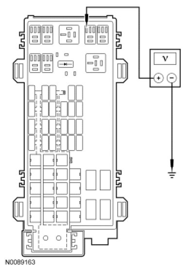
- Is the voltage greater than 10 volts?
Yes
CARRY OUT the A/C clutch relay component test.
If the relay tests OK, GO to B2.
No
REPAIR circuit CBB40 (YE/GN) for an open. CLEAR the DTCs. REPEAT the self-test. TEST the system for normal operation.
-------------------------------------------------
B2 CHECK CIRCUIT CH302 (WH/BN) FOR A SHORT TO VOLTAGE
- Ignition OFF.
- Disconnect: PCM C175b.
- Ignition ON.
- Measure the voltage between ground and PCM C175b-14, circuit CH302 (WH/BN), harness side.
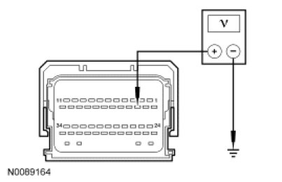
- Is any voltage present?
Yes
REPAIR circuit CH302 (WH/BN) for a short to voltage. CLEAR the DTCs. REPEAT the self-test. TEST the system for normal operation.
No
GO to B3.
-------------------------------------------------
B3 CHECK CIRCUIT CH302 (WH/BN) FOR A SHORT TO GROUND
- Ignition OFF.
- Measure the resistance between ground and PCM C175b-14, circuit CH302 (WH/BN), harness side.
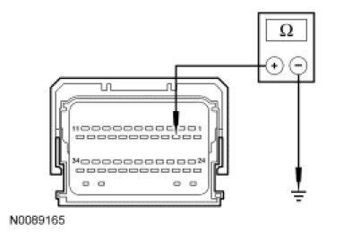
- Is the resistance greater than 10,000 ohms?
Yes
GO to B4.
No
REPAIR circuit CH302 (WH/BN) for a short to ground. CLEAR the DTCs. REPEAT the self-test. TEST the system for normal operation.
-------------------------------------------------
B4 CHECK CIRCUIT CH302 (WH/BN) FOR AN OPEN
- Measure the resistance between A/C clutch relay socket, circuit CH302 (WH/BN) and PCM C175b-14, circuit CH302 (WH/BN), harness side.
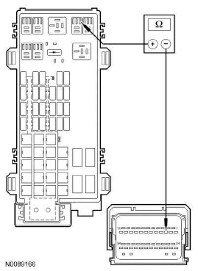
- Is the resistance less than 5 ohms?
Yes
GO to B5.
No
REPAIR circuit 321 (GY/WH) for an open. CLEAR the DTCs. REPEAT the self-test. TEST the system for normal operation.
-------------------------------------------------
B5 CHECK THE PCM CONNECTION
- Clear the DTCs.
- Disconnect all the PCM connectors.
- Check for:
- corrosion.
- pushed-out pins.
- incorrectly seated connector.
- Connect and correctly seat all the PCM connectors.
- Operate the system.
- Does the concern return?
Yes
INSTALL a new PCM. TEST the system for normal operation.
No
The system is operating correctly at this time. The concern may have been caused by a loose or corroded connector.
-------------------------------------------------