Inspection Procedure 5
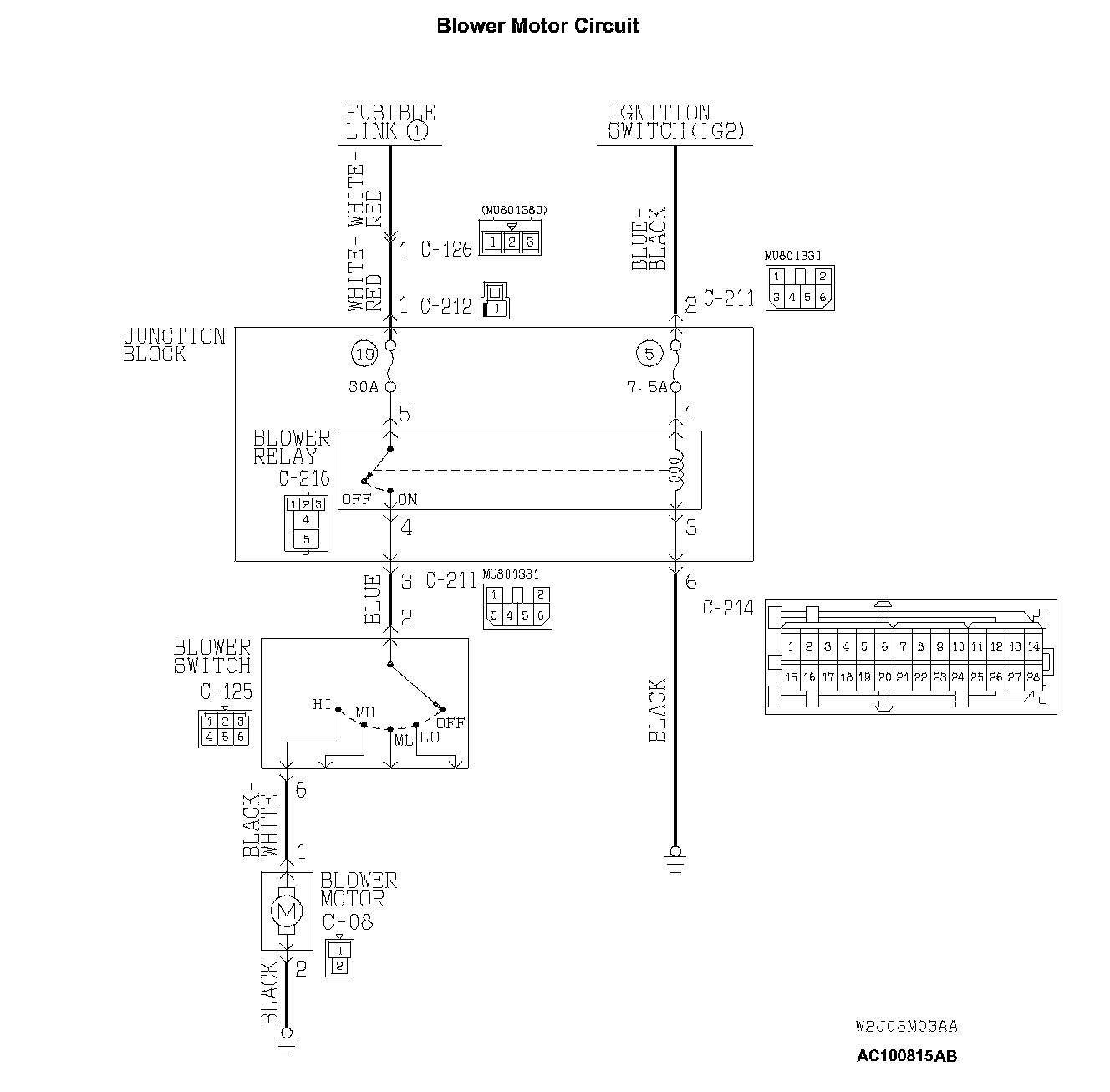
Blower Fan and Motor does not Turn.Blower Motor Circuit Part 1:
Blower Motor Circuit Part 2:
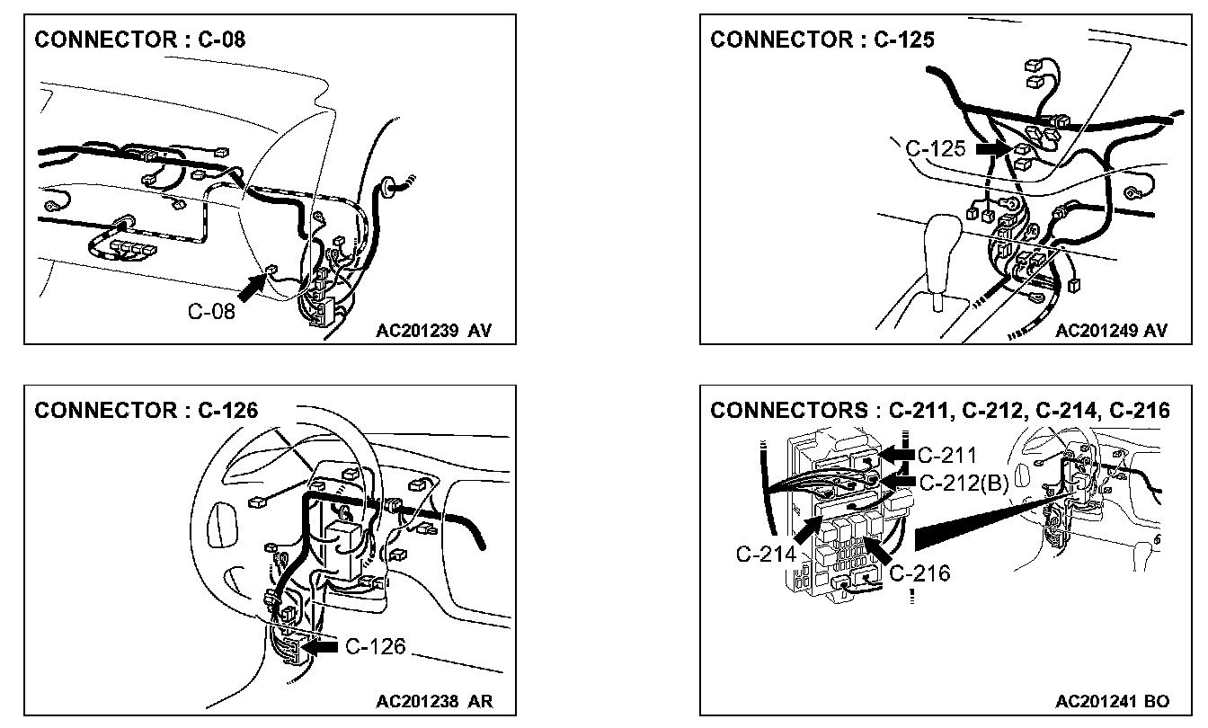
TECHNICAL DESCRIPTION (COMMENT)
If the blower fan and motor does not turn when the blower switch is operated, the blower switch may be defective.
TROUBLESHOOTING HINTS
- Malfunction of the blower relay
- Malfunction of the blower switch
- Malfunction of the blower motor
- Damaged harness wires or connectors
DIAGNOSIS
Required Special Tools:
- MB991223: Test Harness Set
STEP 1. Measure the voltage at blower switch connector C-125.
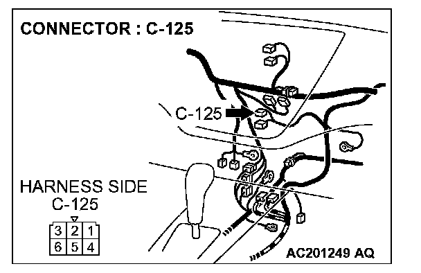
1. Disconnect blower switch connector C-125, and measure the voltage at the wiring harness side.
2. Ignition switch: ON
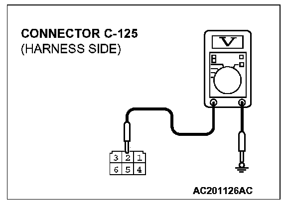
3. Measure the voltage between terminal 2 and ground.
- The measured value should be approximately 12 volts (battery positive voltage).
Q: Does the measured voltage correspond with this range?
YES: Go to Step 14.
NO: Go to Step 2.
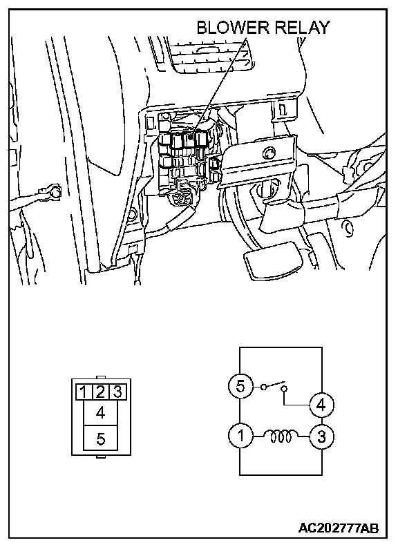
STEP 2. Check the blower relay continuity.
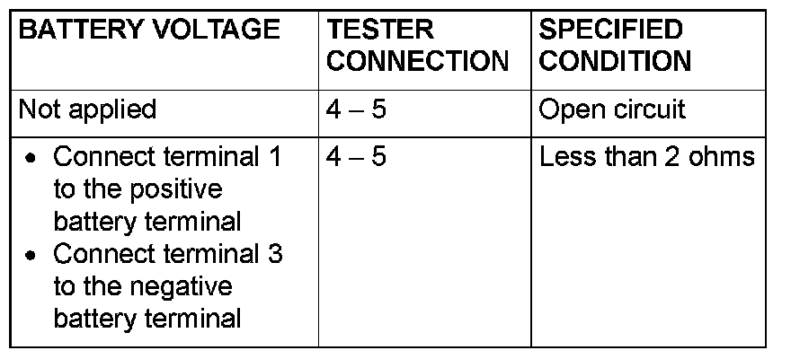
Follow the table to check the blower relay for continuity.
Q: Is the blower relay continuity in good condition?
YES: Go to Step 3.
NO: Replace the blower relay. The blower motor should operate normally.
STEP 3. Measure the voltage at blower relay connector C-216.
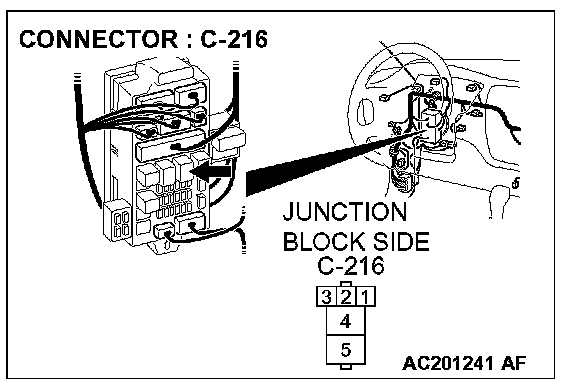
1. Disconnect blower relay connector C-216, and measure the voltage at the junction block side.
2. Ignition switch: ON
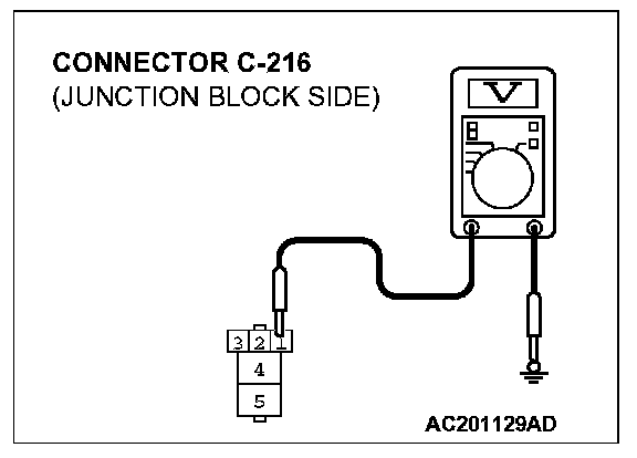
3. Measure the voltage between terminal 1 and ground.
- The measured value should be approximately 12 volts (battery positive voltage).
Q: Does the measured voltage correspond with this range?
YES: Go to Step 6.
NO: Go to Step 4.
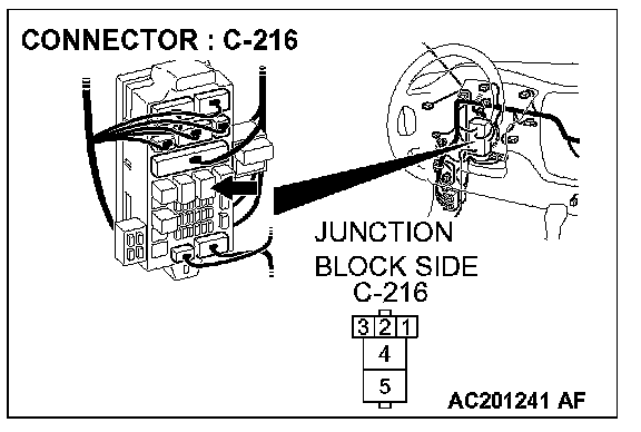
STEP 4. Check blower relay connector C-216 for damage.
Q: Is blower relay connector C-216 in good condition?
YES: Go to Step 5.
NO: Repair or replace the connector. Refer to Harness Connector Inspection.The blower motor should operate normally.
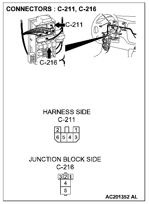
STEP 5. Check the wiring harness between blower relay connector C-216 (terminal 1) and the ignition switch (IG2).
NOTE: Also check junction block connector C-211. If junction block connector C-211 is damaged, repair or replace the connector as described in Harness Connector Inspection.
Q: Is the wiring harness between blower relay connector C-216 (terminal 1) and the ignition switch (IG2) in good condition?
YES: The blower motor should operate normally.
NO: Repair the wiring harness. The blower motor should operate normally.
STEP 6. Measure the resistance at blower relay connector C-216.
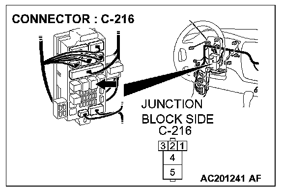
1. Disconnect connector C-216, and measure the resistance at the junction block side.
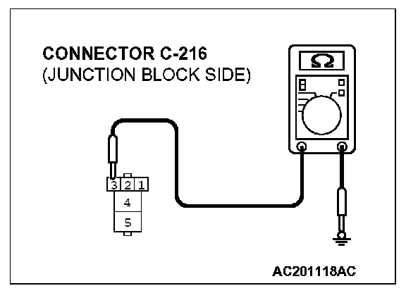
2. Measure the resistance value between terminal 3 and ground.
- 2 Ohm or less
Q: Does the measured resistance value correspond with this range?
YES: Go to Step 9.
NO: Go to Step 7.
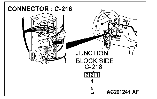
STEP 7. Check blower relay connector C-216 for damage.
Q: Is blower relay connector C-216 in good condition?
YES: Go to Step 8
NO: Repair or replace the connector. Refer to Harness Connector Inspection.The blower motor should operate normally.
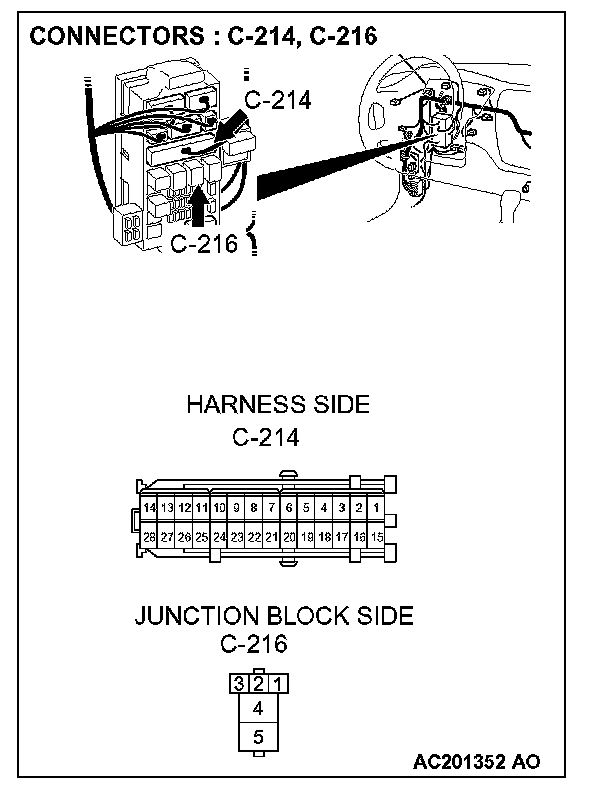
STEP 8. Check the wiring harness between blower relay connector C-216 (terminal 3) and ground.
NOTE: Also check junction block connector C-214. If junction block connector C-214 is damaged, repair or replace the connector as described in Harness Connector Inspection.
Q: Is the wiring harness between blower relay connector C-216 (terminal 3) and ground in good condition?
YES: The blower motor should operate normally.
NO: Repair the wiring harness. The blower motor should operate normally.
STEP 9. Measure the voltage at blower relay connector C-216.
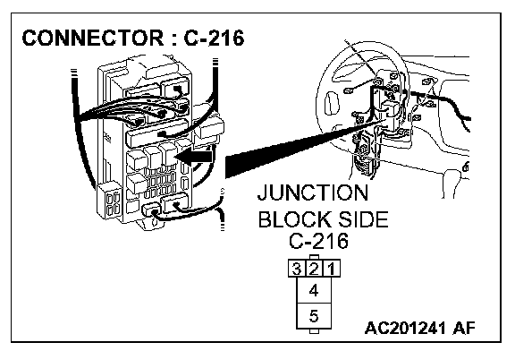
1. Disconnect blower relay connector C-216, and measure the voltage at the junction block side.
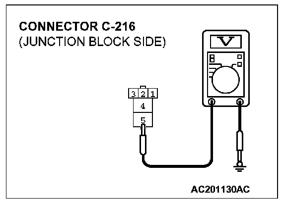
2. Measure the voltage between terminal 5 and ground.
- The measured value should be approximately 12 volts (battery positive voltage).
Q: Does the measured voltage correspond with this range?
YES: Go to Step 12.
NO: Go to Step 10.
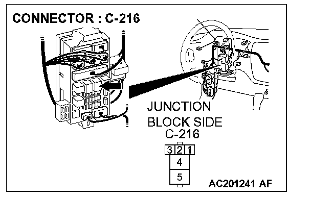
STEP 10. Check blower relay connector C-216 for damage.
Q: Is blower relay connector C-216 in good condition?
YES: Go to Step 11.
NO: Repair or replace the connector. Refer to Harness Connector Inspection.The blower motor should operate normally.
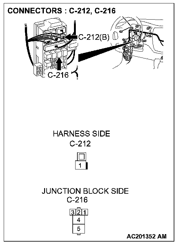
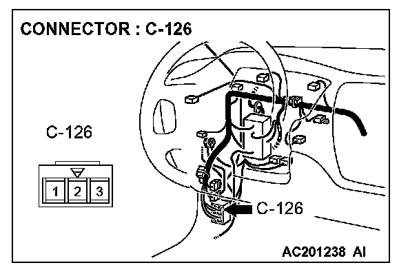
STEP 11. Check the wiring harness between blower relay connector C-216 (terminal 5) and fusible link (1).
NOTE: Also check intermediate connector C-126 and junction block connector C-212. If intermediate connector C-126 or junction block connector C-212 is damaged, repair or replace the connector as described in Harness Connector Inspection.
Q: Is the wiring harness between blower relay connector C-216 (terminal 5) and fusible link (1) in good condition?
YES: The blower motor should operate normally.
NO: Repair the wiring harness. The blower motor should operate normally.
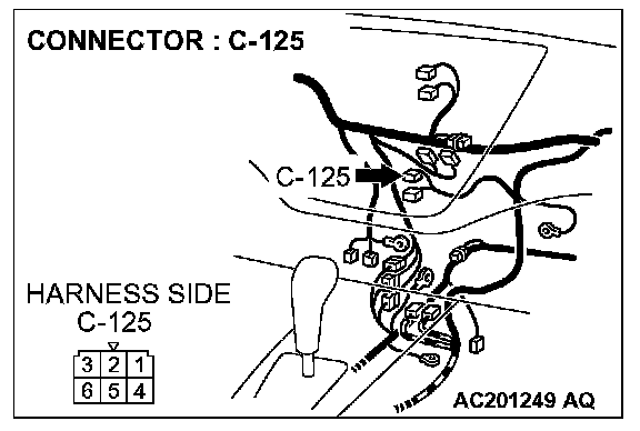
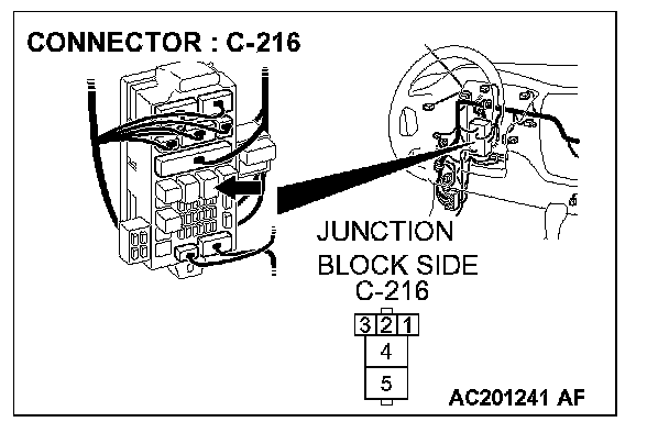
STEP 12. Check blower switch connector C-125 and blower relay connector C-216 for damage.
Q: Is blower switch connector C-125 and blower relay connector C-216 in good condition?
YES: Go to Step 13.
NO: Repair or replace the connector. Refer to Harness Connector Inspection.The blower motor should operate normally.
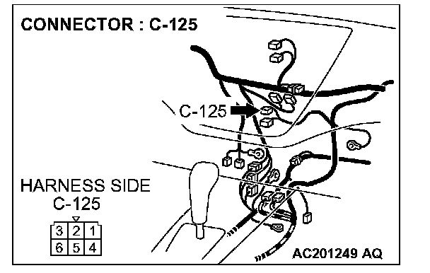
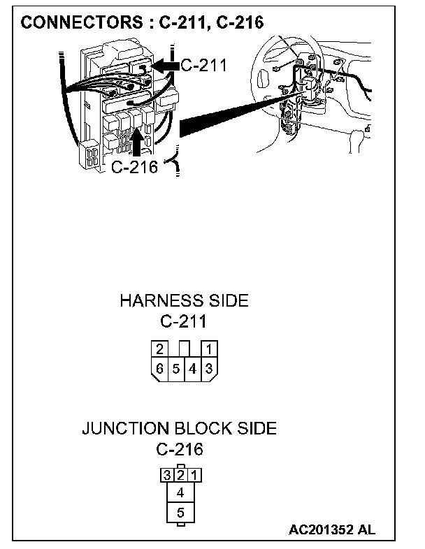
STEP 13. Check the wiring harness between blower switch connector C-125 (terminal 2) and blower relay connector C-216 (terminal 4).
NOTE: Also check junction block connector C-211. If junction block connector C-211 is damaged, repair or replace the connector as described in Harness Connector Inspection.
Q: Is the wiring harness between blower switch connector C-125 (terminal 2) and blower relay connector C-216 (terminal 4) in good condition?
YES: The blower motor should operate normally.
NO: Repair the wiring harness. The blower motor should operate normally.
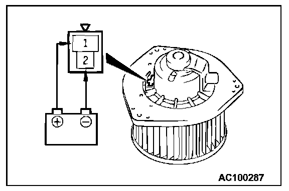
STEP 14. Check the blower fan and motor operation.
When battery voltage is applied between the terminals, check that the motor operates.
Q: Is there any abnormal noise?
YES: Go to Step 15.
NO: Replace the blower relay. The blower motor should operate normally.
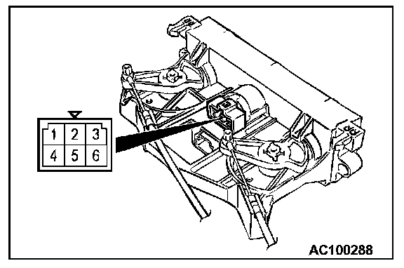
STEP 15. Check the blower switch continuity.
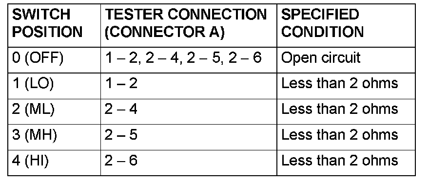
Follow the table to check the blower switch for continuity.
Q: Is the blower switch continuity in good condition?
YES: Go to Step 16.
NO: Replace the blower switch. The blower motor should operate normally.
STEP 16. Measure the resistance at blower motor connector C-08.
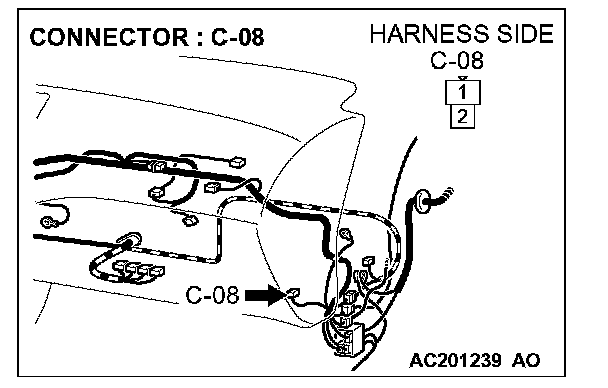
1. Disconnect blower motor connector C-08, and measure the voltage at the wiring harness side.
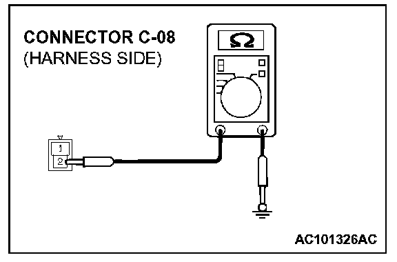
2. Measure the resistance value between terminal 2 and ground.
- 2 Ohm or less
Q: Does the measured resistance value correspond with this range?
YES: Go to Step 19.
NO: Go to Step 17.
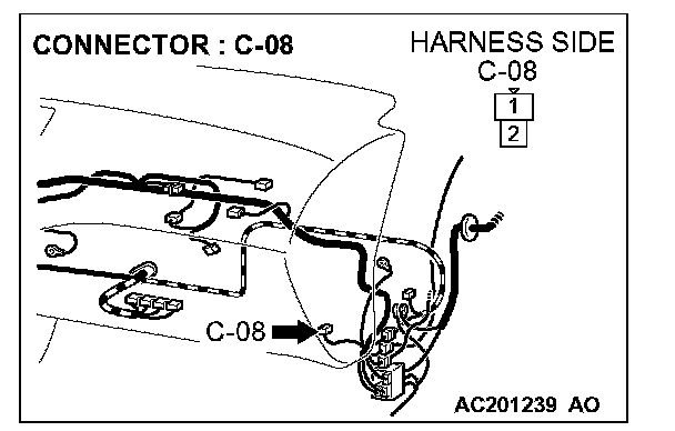
STEP 17. Check blower motor connector C-08 for damage.
Q: Is blower motor connector C-08 in good condition?
YES: Go to Step 18.
NO: Repair or replace the connector. Refer to Harness Connector Inspection.The blower motor should operate normally.
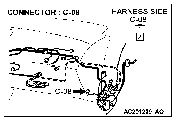
STEP 18. Check the wiring harness between blower motor connector C-08 (terminal 2) and ground.
Q: Is the wiring harness between blower motor connector C-08 (terminal 2) and ground in good condition?
YES: No action to be taken.
NO: Repair the wiring harness. The blower motor should operate normally.
STEP 19. Measure the voltage at blower motor connector C-08.
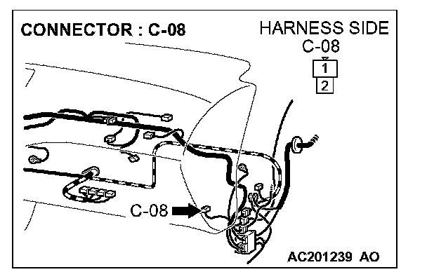
1. Disconnect blower motor connector C-08, and measure the voltage at the wiring harness side.
2. Ignition switch: ON
3. Blower switch: HI
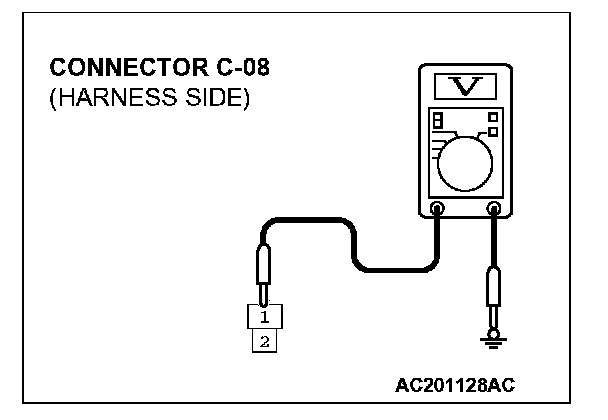
4. Measure the voltage between terminal 1 and ground.
- The measured value should be approximately 12 volts (battery positive voltage).
Q: Does the measured voltage correspond with this range?
YES: The blower motor should operate normally.
NO: Go to Step 20.
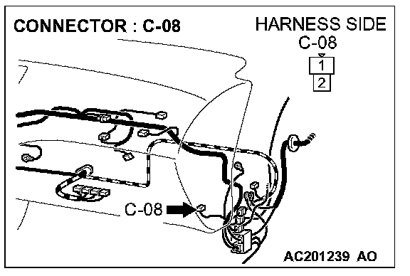
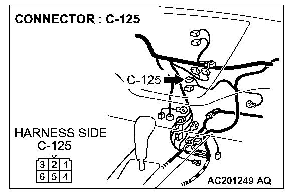
STEP 20. Check blower motor connector C-08 and blower switch connector C-125 for damage.
Q: Is blower motor connector C-08 and blower switch connector C-125 in good condition?
YES: Go to Step 21.
NO: Repair or replace the connector. Refer to Harness Connector Inspection.The blower motor should operate normally.
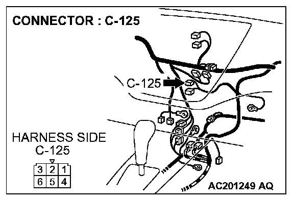
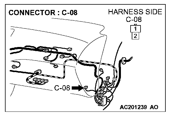
STEP 21. Check the wiring harness between blower motor connector C-08 (terminal 1) and blower switch connector C-125 (terminal 6).
Q: Is the wiring harness between blower motor connector C-08 (terminal 1) and blower switch connector C-125 (terminal 6) in good condition?
YES: The blower motor should operate normally.
NO: Repair the wiring harness. The blower motor should operate normally.