Inspection Procedure 6
Blower Air Amount cannot be Changed.Blower Switch And Resistor Circuit:
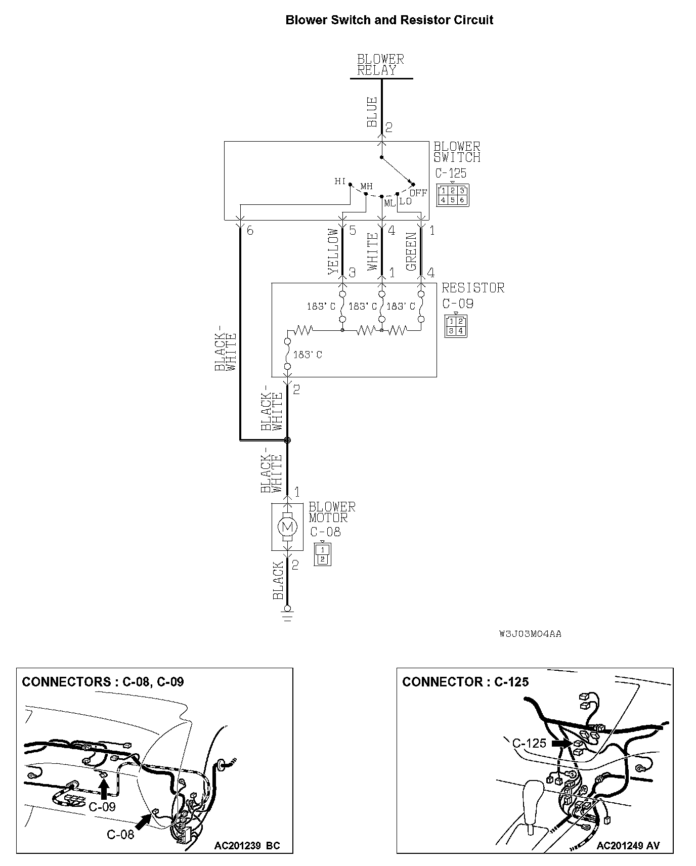
TECHNICAL DESCRIPTION (COMMENT)
If the blower air amount can not be changed when the blower switch is operated, the blower switch may be defective.
TROUBLESHOOTING HINTS
- Malfunction of the resistor
- Malfunction of the blower switch
- Damaged harness wires or connectors
DIAGNOSIS
Required Special Tools:
- MB991223: Test Harness Set
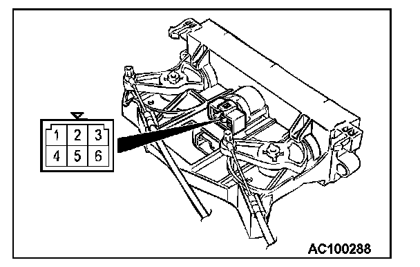
STEP 1. Check the blower switch continuity.
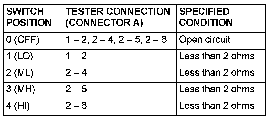
Follow the table to check the blower switch for continuity.
Q: Is the blower switch continuity in good condition?
YES: Go to Step 2.
NO: Replace the blower switch. The blower motor should operate normally.
STEP 2. Check that the blower motor operates when the blower switch is moved to the "HI" position.
1. Ignition switch: ON
2. Blower switch: HI
Q: Does the blower motor operate when the blower switch is moved to the "HI" position?
YES: Go to STEP 5.
NO: Go to STEP 3.
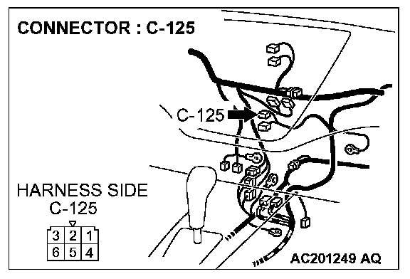
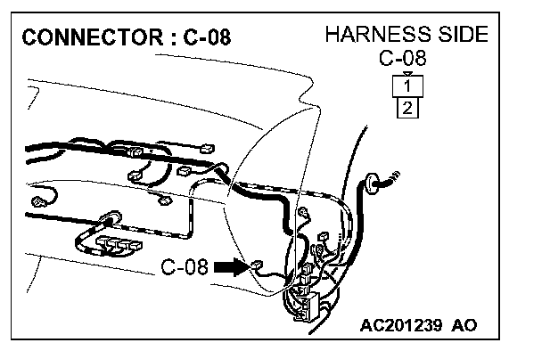
STEP 3. Check blower switch connector C-125 and blower motor connector C-08 for damage.
Q: Are blower switch connector C-125 and blower motor connector C-08 in good condition?
YES: Go to Step 4.
NO: Repair or replace the connector. Refer to Harness Connector Inspection.The blower motor should operate normally.
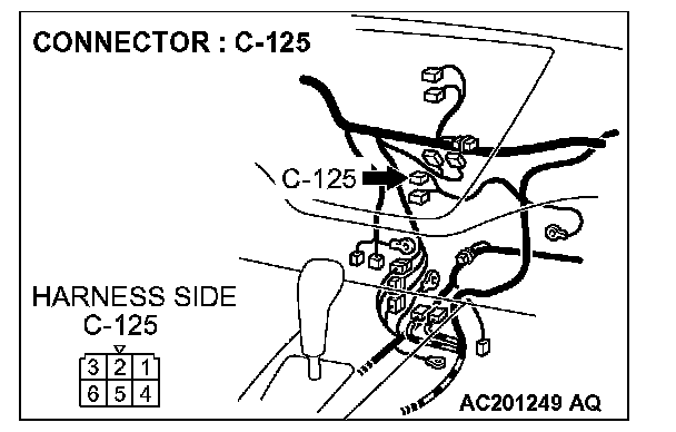
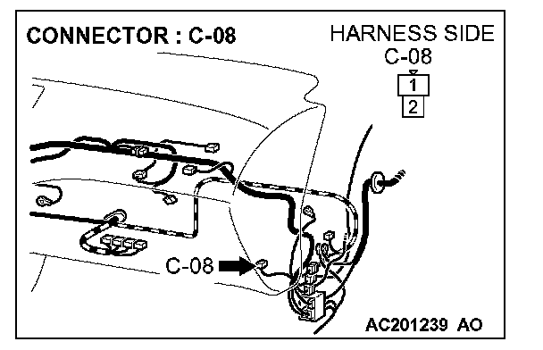
STEP 4. Check the wiring harness between blower switch connector C-125 (terminal 6) and blower motor connector C-08 (terminal 1).
Q: Is the wiring harness between blower switch connector C-125 (terminal 6) and blower motor connector C-08 (terminal 1) in good condition?
YES: The blower motor should operate normally.
NO: Repair the wiring harness. The blower motor should operate normally.
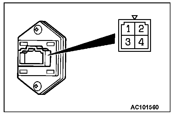
STEP 5. Check the resistor resistance value.
Use an ohmmeter to measure the resistance between the terminals as indicated. Check that the measured value is at the standard value.
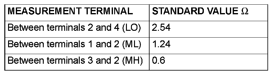
Standard value:
Q: Is the measured value at the standard value?
YES: Go to Step 6.
NO: Replace the resistor. The blower motor should operate normally.
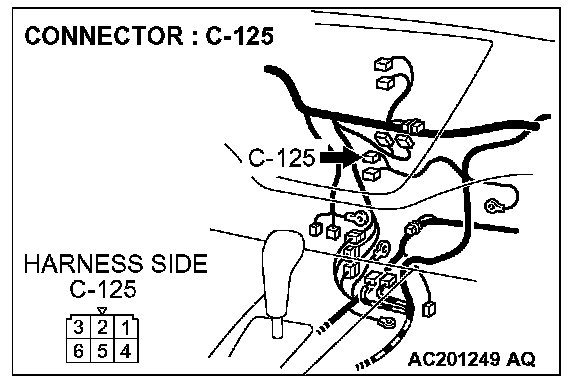
STEP 6. Check blower switch connector C-125 and resistor connector C-09 for damage.
Q: Are blower switch connector C-125 and resistor connector C-09 in good condition?
YES: Go to Step 7.
NO: Repair or replace the connector. Refer to Harness Connector Inspection. The blower motor should operate normally.
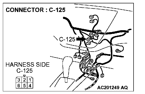
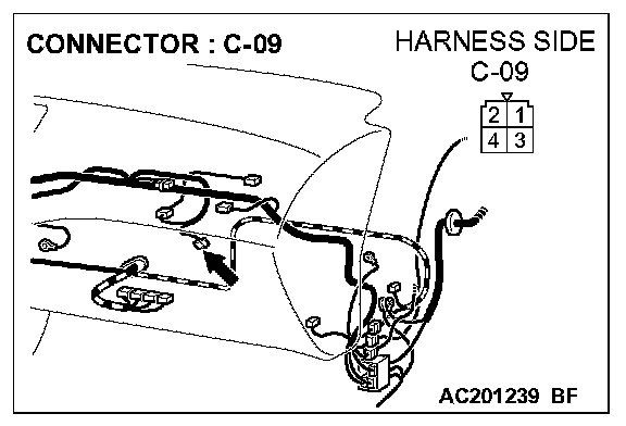
STEP 7. Check the wiring harness between blower switch connector C-125 (terminals 1, 4 and 5) and resistor connector C-09(terminals 4, 1 and 3).
Q: Is the wiring harness between blower switch connector C-125 (terminals 1, 4 and 5) and resistor connector C-09(terminals 4, 1 and 3) in good condition?
YES: Go to Step 8.
NO: Repair the wiring harness. The blower motor should operate normally.
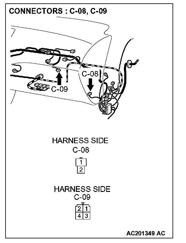
STEP 8. Check resistor connector C-09 and blower motor connector C-08 for damage.
Q: Are resistor connector C-09 and blower motor connector C-08 in good condition?
YES: Go to Step 9.
NO: Repair or replace the connector. Refer to Harness Connector Inspection. The blower motor should operate normally.
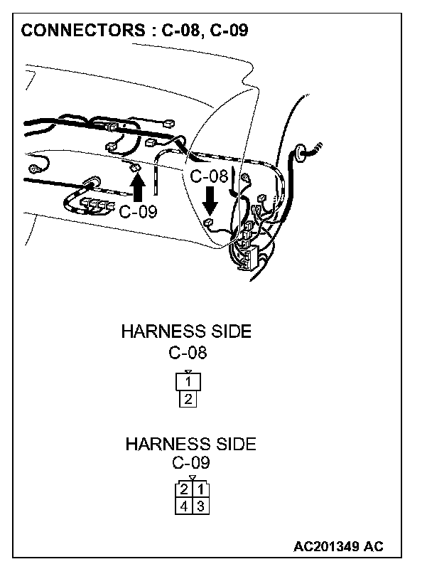
STEP 9. Check the wiring harness between blower motor connector C-08 (terminal 1) and resistor connector C-09 (terminal 2).
Q: Is the wiring harness between blower motor connector C-08 (terminal 1) and resistor connector C-09 (terminal 2) in good condition?
YES: No action to be taken.
NO: Repair the wiring harness. The blower motor should operate normally.