Transaxle Assemble
Transaxle Assemble
Tools Required
* 78 41 067 Sleeve, Inner Drive
* 83 90 114 Sleeve
* 87 90 867 Input Shaft Bearing Ring
* 87 91 204 Output Shaft Bearing Race Sleeve
* 87 91 261 Output Shaft Remover
* 87 91 311 Sleeve, Bearing Driver Shaft
* 87 91 428 Driver
* 87 92 053 Companion Flange
* 87 92 061 Output Shaft Nut Socket
* 87 92 095 Kilogram Weight
* 87 92 103 Output Shaft Assembly Tool
* 87 92 137 Milled Bearing Race
* 87 92 202 Output Shaft Bearing Race Sleeve
* J 43707 Transmission Support Fixture
* J 44362 Input Shaft Support
* J 7754-C Inch Pound Torque Wrench
* SA9179NE Dial Indicator
Important: In all work involving disassembly of transaxle, a new output shaft nut and crush sleeve must be installed during reassembly.
Important: Ensure the transaxle case, clutch housing and end cover are clean from all debris and gasket material prior to transaxle assembly.
Important: Lubricate all rotating parts and bearings with manual transaxle lubricant P/N 21018899 during assembly.
1. Mount the clutch housing on the J 43707, if necessary.

2. Install differential assembly into clutch housing.

3. Make sure the output shaft oil feed tube is staked in place in the clutch housing prior to installing the output shaft.

4. Install the output shaft.
1. Install the output shaft into the clutch housing bore.
2. Lubricate the bearing.
3. Install the output shaft bearing race by tapping the race with a plastic hammer to start in the bore.
Important: Install the bearing retainer plate to ensure correct depth of the bearing race.
4. Install the bearing retainer.
5. Tap down the bearing race using the retainer and tools. The 87 92 202 and the 87 91 204 as shown.
Notice: Refer to Fastener Notice in Service Precautions.
5. Apply LOCTITE 242(R) Threadlocker P/N 21485277 to 3 middle output shaft bearing retainer bolts and install.
Tighten the output shaft bearing retainer bolts (inner) to 45 N.m (33 lb ft).
6. Apply LOCTITE 242(R) Threadlocker P/N 21485277 to 1 outer output shaft bearing retainer bolt and install.
Tighten the output shaft bearing retainer bolts (outer) to 24 N.m (18 lb ft).

Important: There must be a 15 mm (0.6 in) clearance between the 1st driven gear and the clutch housing to be able to install the input shaft. This can be done by putting the output shaft nut between the clutch housing and the 1st driven gear.
7. Install an object on top of the main shaft bearing retainer so that there will be a 15 mm (0.6 in) clearance between the bearing retainer and the 1st/2nd driven gear assembly when it is installed.
8. Install the 1st/2nd driven gear assembly, held together with the 87 92 103 on the output shaft.
Important: The third driven gear must be installed in the same orientation as it was removed to avoid noise concerns.
9. Install the 3rd driven gear and spacer sleeve on the output shaft.

10. Lubricate the input shaft bearing and install the input shaft into the clutch housing. Remove the object holding up the 1st/2nd driven gear assembly from under the 1st driven gear, and install a plastic tie as shown to hold the input and output shaft together.
11. Carefully tap down the output shaft gears to make sure that the gears are against the surface of the clutch housing. This can be done with the 87 91 204 and the 87 90 867.

Important: A new output shaft crush sleeve must be used.
Important: The 4th driven gear should be installed with the machined groove facing down, towards 3rd gear.
12. Install the new crush sleeve and 4th driven gear.

Important: Do not compress the crush sleeve when installing the 4th driven gear. Any compression of the sleeve done other than by tightening the output shaft nut will require disassembly of the transaxle and replacement of the crush sleeve.
13. Install the 87 91 204 on top of the 4th driven gear and tap down the 4th driven gear until contact is made with the crush sleeve.
14. Remove the plastic ties and the 87 91 204.

Important: Make sure the reverse idler gear shaft lube hole is facing the correct way. Refer to the illustration. If the hole is not facing the correct direction, reposition the shaft before installation.
15. Lift the input shaft slightly and install the reverse idler gear shaft assembly. The shaft lubrication hole should be facing the lube passage in the clutch housing.

16. Install the shift linkage mechanism into the clutch housing.
1. Put the 1st/2nd synchronizer sleeve on the output shaft in the 2nd gear position.
2. Put the 3rd/4th synchronizer sleeve on the input shaft in the 4th gear position.
3. Insert the 1st/2nd and 3rd/4th shift forks into the synchronizer sleeves and push the mechanism into place. Upon installation, synchronizer sleeves will drop down into neutral position.
4. Install the locating sleeves and loosely install the outboard shift linkage bolt.
5. Ensure that the wave washer is installed on top of the shift mechanism as shown.

Notice: If thread sealant is not used on the short reverse shift lever assembly bolt, a fluid leak could occur.
Important: The reverse shift lever assembly oil plate should be under the edge of the shift linkage mechanism.
17. Install the reverse shift lever assembly. Loosely install the longer mounting bolt. Apply LOCTITE 592(R) Thread Sealant P/N 1485278, or equivalent, on shorter bolt.
18. Install the shorter reverse shift lever bolt.
19. Tighten the reverse shift lever assembly bolts and shift linkage bolt.
Tighten the bolts to 24 N.m (18 lb ft).

20. Install the reverse gear fork to reverse gear synchronizer sleeve. Make sure the fork is in position on the reverse shift lever and install the reverse gear fork shaft.
21. Engage the reverse gear using the shift linkage assembly to check for full engagement of the reverse.

22. Shift the transaxle into all gear positions with the shift mechanism to check for proper operation. Also check the shift interlocking feature by trying to engage the 1st and reverse gears at the same time. This should be impossible.

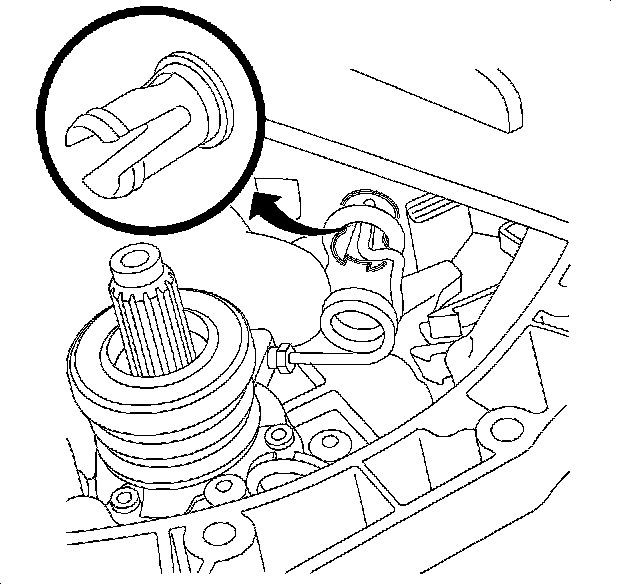
Notice: Care must be taken when applying gasket material to the clutch housing. If any gasket material gets in the transaxle filter vent, noted by the arrow in the illustration, it will plug the vent and cause transaxle oil leaks.
23. Apply a bead of LOCTITE 515(R) gasket eliminator P/N 21005993 or equivalent, down the center of the mating flange on the clutch housing. The bead should be 1-3 mm (0.039-0.118 in) wide.

24. Check for proper alignment of the reverse idler shaft support bracket to the threaded hole in shaft using the bolt. The bracket bolt has to be installed after the transaxle case is installed.
25. Remove bolt from reverse idler shaft and bracket.
Important: Use the shift lever to shift into 3rd gear. Do not use synchronizer.
26. Shift the transaxle into 3rd gear using the shift lever in order to prevent shift mechanism shafts from moving during case installation.

Important: Ensure that the wave washer is installed on top of the shift mechanism as shown in step 16, prior to clutch housing case installation.
27. Install the transaxle case onto the clutch housing. The mark on the gear selector arm must be aligned with the mark on the gear case. The weighted shift arm must be in the position as shown.

28. When the transaxle case is fitted to the clutch housing and the distance between them is approximately 25 mm (a), rotate the shift arm clockwise while lowering the transaxle case so that the guide roller falls into the groove.

29. Install the transaxle case onto the clutch housing and hand start 2 case-to-clutch housing bolts.
30. Tap up the case to clutch housing alignment sleeves.
31. Loosely install the reverse idler gear shaft bracket bolt.
32. Install and tighten all case-to-clutch housing bolts in a criss-cross pattern.
Tighten the transaxle case-to-clutch housing bolts to 24 N.m (18 lb ft).

33. Install and tighten the reverse idler shaft bolt. Check the condition of the O-ring and replace if necessary.
Tighten the reverse idler gear shaft bracket bolt to 24 N.m (18 lb ft).

34. Tighten the reverse idler gear shaft bracket bolt.
Tighten the reverse idler gear shaft bracket bolt to 24 N.m (18 lb ft).
35. Verify the shifter arms can engage all gears. Refer to Shift Control Lever and Selector Control Lever Position/Rotation Specifications.

Notice: Do not compress the crush sleeve when installing the output shaft bearing. Any compression of the sleeve done other than by tightening the output shaft nut will require disassembly of the transaxle and replacement of the crush sleeve.
36. Lubricate and install the output shaft bearing using the 87 91 261. Tighten the 87 91 261 until a solid stop is felt. Do not compress the sleeve.

Important: Ensure that the 3 machine cutouts on the 5th driven gear are facing away from the bearing.
37. Install the 5th driven gear onto the output shaft. Tap down with the 78 41 067 far enough to allow installation of the 87 91 261.
38. Install the 87 91 261 and tighten the tool until the 5th driven gear is against the output shaft bearing. Install a new output shaft nut, but do not tighten.

Important: Carefully tap the input shaft with a plastic hammer from the engine side so the input shaft bearing race is against the input shaft bearing retainer.
Important: If a dial indicator with a magnetic base is used, it will not work with an aluminum case. Locking C-clamp pliers can be used to hold the indicator base to the transaxle case.
39. Install the 87 91 428 to the input shaft and install the SA9179NE, or equivalent, on the input shaft bearing inner race. Attach a drill to the 87 91 428 and spin the transaxle to seat the bearings. Turn the transaxle input shaft about 20 revolutions while pushing and pulling on the drill. While turning, measure the axial play on the dial indicator. Axial play should be between 0.09-0.15 mm (0.004-0.0006 in).
40. Adjust axial play as needed by adding or removing shims under the input shaft bearing retainer.

Important: Make sure that the center wing-headed bolt is backed out completely before installing the support tool.
41. Install the J 44362 on the transaxle as shown. Turn the center wingheaded bolt until contact is made with the input shaft, then turn an additional quarter to a half turn.

42. Lubricate and install the 5th drive gear bearing, 5th drive gear, 5th gear blocking ring, 5th gear leaf springs and blocking ring spring.

Important: The tangs on the blocking rings must fit in the hub gaps. Ensure that the blocking ring spring is engaged on the blocking ring and does not get pinched between the hub and the blocking ring.
43. Carefully tap down the 5th synchronizer hub onto the input shaft splines using the 87 91 311 and a hammer.

Important: The 5th gear synchronizer sleeve can only be placed on the hub when the tall teeth on the sleeve are aligned with the deep tooth grooves on the hub.
44. Install the 5th gear synchronizer sleeve. Reference the sleeve alignment mark made during disassembly.

45. Loosely install the output shaft nut.
Important: Do not pry under the gear teeth. Make sure the screwdriver is as far past the gear teeth as possible.
46. Install the SA9179NE, or equivalent, on top of the 5th driven gear. Engage the 1st gear on the transaxle and engage the 5th gear by pressing down the 5th gear synchronizer sleeve. Install a bolt in the case as shown so that you are not prying against the rear cover sealing surface. Measure the output shaft end play by prying up on the 5th driven gear and watching the dial indicator.
Tighten the output shaft nut until end play is between 0.06-0.05 mm (0.002-0.002 in).

47. Disengage the 1st gear and remove the 5th gear synchronizer sleeve.

48. Check and adjust the preload of the differential bearings as follows:
1. Install the 87 92 137 in place of the left differential bearing race.
2. Install about 2 mm of shims on top of the ground bearing race.
3. Remove the O-ring from the differential bearing retainer and install without any fasteners.

Important: Make sure the drill is spinning in a clockwise direction. The 87 92 053 will unravel if the drill is spinning in the wrong direction.
49. Measure the differential bearing pre-load.
1. Place the 87 92 095 on top of the differential bearing retainer.
2. Install the 87 92 053 on the output shaft.
3. Use a drill to rotate the differential at least 20 revolutions.
4. Use a feeler gage and measure between the transaxle case and differential bearing retainer in 3 different places.
5. Take the average of the 3 readings and adjust the shims so that the average measurement corresponds to the following readings:
* The transaxle condition of the old clutch housing, if greater than 49 900 kilometers (31,000 miles) with old differential bearings, has a nominal value of 0.2 mm (0.008 in).
* The transaxle condition of the old clutch housing, if greater than 49 900 kilometers (31,000 miles) with NEW differential bearings, has a nominal value of 0.3 mm (0.012 in).
* The transaxle condition of the new clutch housing with new differential bearings has a nominal value of 0.35 mm (0.014 in).
50. Adjust the shims using the following information:
* More shims equals increased preload.
* Less shims equals decreased preload.
* Shims are available in 0.10 mm, 0.15 mm, 0.30 mm, and 0.5 mm thicknesses.
Notice: Do not forget to remove the milled bearing race. Leaving it in will damage the transaxle.
51. Remove the 10 kg weight, differential bearing retainer, and 87 92 137.

Important: The differential bearing retainer will not be torqued to specification until the final output shaft preload is set. If the differential bearing retainer is torqued down at this point, it will interfere with the final output shaft measurements.
52. Install the differential bearing retainer.
1. Install the differential bearing race and tap down using the 83 90 114.
2. Install the shim pack determined in the last step.
3. Lubricate the O-ring and install on the differential bearing retainer.
4. Install the differential bearing retainer.
5. Tighten the retainer bolts until the retainer is 0.15 mm (0.006 in) from the transaxle case.

53. Turn the transaxle to the horizontal, in car, position.
Important: Make sure that the transaxle is in NEUTRAL.
54. Measure the input shaft bearing pre-load.
1. Remove tool 87 91 428 from the hose.
2. Install a 3/8 in. drive - 16 mm (0.6 in) deep well socket into one end of the hose.
3. Insert the other end over the input shaft as shown.
4. Install the J 7754-C, or equivalent, to the socket and rotate clockwise several rotations at an even speed.
5. Read the average value on the torque wrench during rotations. The torque should be between 0.1-0.3 N.m (1-3 lb in).
If the torque is higher or varies greatly while rotating the input shaft, there may be contamination in the bearings. The transaxle should be disassembled to determine the cause of excessive torque.

Important: Ensure that the drill is spinning in a clockwise direction. The 87 92 053 will unravel if the drill is spinning in the wrong direction.
Important: Ensure that the 87 92 053 does not damage the dial indicator when spinning the output shaft.
Important: The measurement taken in this step must be in millimeters. If the measurement is in inches, multiply it by 25.4 to convert to millimeters.
55. Measure the output shaft end play.
1. Turn the transaxle back to the vertical position.
2. Place the dial indicator tip on the 5th driven gear as shown.
3. Install the 87 92 053 on the output shaft.
4. Turn the output shaft several revolutions to seat the bearings.
5. Press down on the drill and turn the output shaft for 20 revolutions.
6. Zero the dial indicator.
7. Pull up on the drill and turn for another 20 revolutions.
8. Take a measurement when the reading stabilizes. This output shaft end play measurement will be used in tightening the input shaft nut in a later step. Convert the measurement to millimeters if necessary.
9. Remove all tools.

56. Engage the 1st gear on the transaxle and engage the 5th gear by pressing down the 5th gear synchronizer sleeve.
57. Install the 5th gear synchronizer sleeve.

58. Install the 87 92 061 on the output shaft nut.
59. Calculate the number of line that the 87 92 061 must be turned to tighten the output shaft nut by doing the following:
1. Add the output shaft end play value that was determined in a previous step with the nominal value from the list below. Ensure that the output shaft end play is in millimeters or has been converted to millimeters.
2. Multiply the sum found in the previous step by 100.
3. With a marker, place a mark on the gear tooth corresponding to the line on the socket that matches the number calculated. This is the number of lines that the 87 92 061 must be turned.
Example: The output shaft end play reading found previously is 0.38 mm + nominal value 0.08 mm = 0.46 mm. Multiply 0.46 by 100 = 46. This is the number of lines that the 87 92 061 must be turned.
* The transaxle condition of the old clutch housing, if greater than 49 900 kilometers (31,000 miles) with the old differential bearing greater than 49 900 kilometers (31,000 miles), has a nominal value of 0 mm (0 in).
* The transaxle condition of the old clutch housing, if less than 49 900 kilometers (31,000 miles) with the old output shaft bearing less than 49 900 kilometers (31,000 miles), has a nominal value of 0.03 mm (0.0012 in).
* The transaxle condition of the old clutch housing, if less than 49 900 kilometers (31,000 miles) with a new output shaft bearing, has a nominal value of 0.8 mm (0.003 in).
* The transaxle condition of the new clutch housing with a new output shaft has a nominal value of 0.15 mm (0.006 in).

60. Tighten the output shaft nut in 2-3 stages until the zero (0) on the socket is at the marked gear tooth.
61. Before taking a more precise measurement of the output shaft bearing preload, make sure the following condition are true:
* The input shaft bearing end play is 0.09-0.15 mm (0.003-0.006 in).
* The differential bearing retainer is installed but not tight. The end play is 0.15 mm (0.006 in).
62. Turn the transaxle to the horizontal, in car, position. Disengage the 1st gear and remove the 5th gear synchronizer sleeve.

63. Check the input shaft and output shaft bearing preload.
1. Ensure that the transaxle is in Neutral.
2. Install the J 7754-C, or equivalent, on the output shaft nut.
3. Rotate the wrench clockwise at an even speed.
4. Read the average value during rotation.
5. Subtract the average value from the input shaft, taken in step 43, from the average value of the output shaft. The calculated preload is the measurement of the output shafts turning torque, normally 0.75-0.25 N.m. (6.75-2.25 lb in).
Example:
Output Shaft Reading: 1.10 N.m (10 lb in)
Input Shaft Reading: 0.30 N.m (2.7 lb in)
Preload: 1.10-0.30 = 0.80 N.m (7.2 lb in)
If the average torque is less than 0.5 N.m (4.5 lb in)
Cause: Bearings are not sufficiently tight.
Correction: Tighten the output shaft nut by 2 lines on the 87 92 061. Take another measurement. Repeat the process until the correct torque is reached.
If the average torque varies greatly:
Cause: Contamination in the bearings or faulty synchronizer blocking rings.
Correction: Disassemble the transaxle, inspect the components, and repair as necessary.
If the average torque is higher than 1.0 N.m (9 lb in)
Cause: Bearings are too tight or contamination in the bearings.
Correction: Install a new crush sleeve in the transaxle and reset the bearing preloads.

64. Lock the output shaft nut using a chisel and a hammer.
65. Turn the transaxle to the vertical position. Put the transaxle in 3rd gear.
Important: The 5th gear fork and synchronizer sleeve together can only be placed on the hub when the tall teeth on the sleeve are aligned with the deep tooth grooves on the hub.
66. Install the 5th gear fork and synchronizer sleeve together. Reference the sleeve alignment mark made during disassembly.
67. Install a new synchronizer hub snap ring.
68. Install a new 5th gear fork retaining pin.

69. Tighten the differential bearing retainer bolts.
Tighten the differential bearing retainer-to-transaxle bolts to 24 N.m (18 lb ft).
70. Clean the rear cover gasket surfaces. Surfaces must be clean and dry.
71. Install the rear cover gasket.
72. Install the rear cover and bolts and torque using a criss-cross pattern.
Tighten the rear cover-to-transaxle bolts to 24 N.m (18 lb ft).

Important: If installing a new backup lamp switch, it will have thread sealant P/N 21485278 already applied on the threads.
73. Apply thread sealant P/N 21485278 and install the backup lamp switch.
Tighten the backup lamp switch to 24 N.m (18 lb ft).

74. Ensure that the magnet is in the transaxle drain plug (1).
75. Clean and apply thread sealant P/N 21485278 to the transaxle drain plug (1) and fill plug (2).
76. Install the transaxle drain plug (1) and fill plug (2).
Tighten the transaxle drain plug to 50 N.m (37 lb in).
Notice: Use care when applying transmission fluid to the input shaft seal. Avoid damaging the seals within the clutch actuator.
77. Lightly apply transmission fluid P/N 21018899 between the lips of the input shaft seal.
Notice: Thread sealant must be used on the slave cylinder bolts to prevent a transaxle oil leak.
78. Install the slave cylinder. Use LOCTITE 592(R) P/N 21485278 thread sealant on the screws
Tighten the slave cylinder fasteners to 10 N.m (7 lb ft).
79. Install the clutch actuator cylinder pipe and pipe sleeve.