Transaxle Disassemble
Transaxle Disassemble
Tools Required
* 87 91 188 Screw Press Support
* 87 91 204 Output Shaft Bearing Race Sleeve
* 87 91 261 Output Shaft Remover
* 87 91 287 Puller
* 87 91 295 Puller Arms, 300 mm
* 87 91 303 Puller Arms, 150 mm
* 87 91 410 Output Shaft Protector
* 87 91 972 Assembly Ring
* 87 92 103 Output Shaft Assembly Tool
* 87 92 129 Lifting Eye
* 87 92 202 Output Shaft Bearing Race Sleeve
* J 25031-A Three Jaw Puller
* J 43483 Impact Driver
* J 43707 Transaxle Support Fixture
* J 43964 Engine Stand Fixture Adapter

Important: In all work involving disassembly of the transaxle, a new output shaft nut and crush sleeve must be installed during reassembly.
1. Remove the backup lamp switch to prevent the switch from being damaged during disassembly.
2. Cover the holes for clutch hydraulics, axles, and the reverse lamp switch, and clean the transaxle if necessary.

3. Mount the transaxle on J 43707. Mount the transaxle and fixture in the J 43964.

4. Remove the pipe from the slave cylinder.
5. Using pliers, pinch together the bottom halves of the pipe sleeve and move the pipe and sleeve upward.
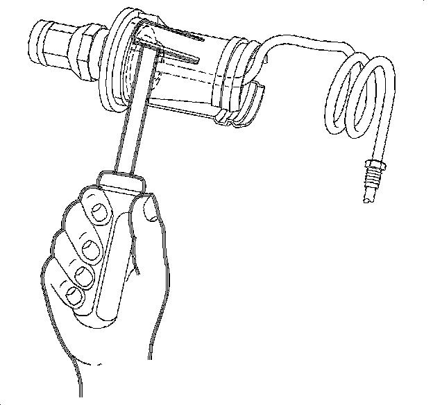
6. Pry up the locking tabs on the sleeve and remove the pipe.

7. Remove the slave cylinder bolts and slave cylinder.
8. Remove the reverse idler gear shaft bolt with an O-ring.

9. Remove the transaxle rear cover and discard the gasket.

Important: Do not shift gears using the 1st/2nd, 3rd/4th, or 5th shift shafts. All shifting should be done using the shift arms.
10. Engage 1st gear to lock the gear box. Refer to the shift arm positions in the illustration.
11. Using a punch and hammer, tap out the 5th gear fork retaining pin and remove from shift fork.

12. Engage the 5th gear by pressing the synchronizer sleeve and fork down onto the 5th gear. Two gears must be engaged at the same time to allow removal of output shaft nut.
13. Pry up the locking tab on the output shaft nut and remove the nut.

Important: Before removing the 5th gear synchronizer sleeve, mark its position relative to the 5th gear synchronizer hub to assist in assembly.
Important: Make sure the 5th gear shift shaft does not come out of the transaxle when the 5th gear shift fork is removed.
14. Remove the 5th gear shift fork and synchronizer sleeve together.

15. Remove the 5th gear synchronizer hub snap ring. This will be easier if the hub is tapped down first.
16. Use the J 25031-A to remove the 5th gear synchronizer hub.
17. Remove the blocking ring, blocking ring spring, 5th gear, and 5th gear bearing assembly.

18. Remove the differential bearing retainer fasteners. The retainer will be removed after case removal.

19. Remove the case-to-reverse idler gear shaft bracket bolt.
20. Remove the case-to-clutch housing bolts and tap down 2 case-to-clutch housing alignment sleeves.

21. Remove the case from the output shaft.
1. Check that 3rd gear is engaged.
2. Install the 87 92 129 to the case.
3. Install the 87 91 410 to the output shaft.
4. Install the 87 91 287 with the 87 91 303 into the pulling eyes.
5. Carefully tighten the puller until the output shaft bearing and 5th driven gear releases from the output shaft.

22. Remove tools. Lift off transaxle case.
23. Remove differential bearing retainer from transaxle case.
24. Inspect the O-ring seal and axle seal for damage. Replace if damaged.

Important: Do not re-install the bearing race until after the shimming procedure.
25. Tap out differential bearing race using 87 92 202 and 87 91 204.

26. Remove the reverse gear fork and shaft.

27. Remove the reverse shift lever assembly and bolts.

28. Disengage the reverse on the shift linkage assembly. Remove the remaining shift linkage bolt and lift the mechanism slightly. Remove the locating sleeves.
29. Put the transaxle in 2nd gear and remove the shift linkage assembly by moving it rearward, towards the differential, and angling it out while lifting.

30. Install the reverse idler gear shaft bracket bolt finger tight.
31. Lift the input shaft far enough to allow removal of the reverse idler gear shaft assembly. Remove the reverse idler gear shaft.

32. Remove the 4th driven gear, crush sleeve, and spacer sleeve from the output shaft.

33. Install the 87 92 103 around the 1st gear and 1st/2nd gear synchronizer sleeve as shown. This tool holds the 1st and 2nd synchronizer assemblies together. Secure the tool with a plastic tie.

34. Install the 87 91 410 on the output shaft.
35. Install the 87 91 287 with the 87 91 295 under the 1st driven gear of the output shaft.
36. Carefully tighten the puller until the remaining output shaft gears are up far enough to allow the removal of the input shaft, approximately 15 mm (0.6 in).
37. Remove the input shaft.

Important: Note the up/down orientation of the 3rd driven gear. If the old gear is reinstalled, it must be installed in the same orientation to avoid noise concerns.
38. Continue pulling the driven gears on the output shaft until all gears are loose.
39. Remove the puller and gears from the output shaft.

Notice: The output shaft bearing retainer bolts were installed using a threadlocker at the factory. A J43483 impact driver or equivalent must be used to remove these bolts or the bolt heads may strip out requiring additional repair time.
40. Remove the output shaft bearing retainer bolts using the J 43483 or equivalent and remove the retainer.

41. Remove the output shaft using the 87 91 188, the 87 91 972, and the 87 91 261.

42. Remove the differential assembly.