Pinout Values and Diagnostic Parameters
WINDOW / GLASS: POWER WINDOW CONTROL SYSTEM: TERMINALS OF ECU; 2013 MY FR-S [03/2012 -]
1. POWER WINDOW REGULATOR MASTER SWITCH ASSEMBLY
(a) Disconnect the E8 power window regulator master switch assembly connector.

(b) Measure the voltage and resistance according to the value(s) in the table below.
HINT
Measure the values on the wire harness side with the connector disconnected.
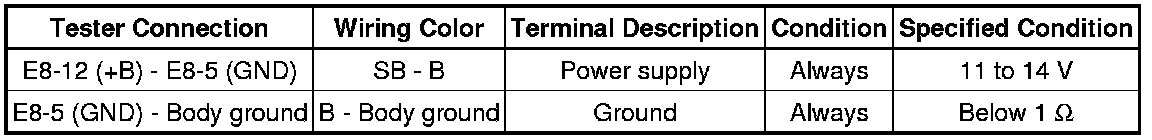
If the result is not as specified, there may be a malfunction in the wire harness.
(c) Reconnect the E8 power window regulator master switch assembly connector.
(d) Measure the voltage according to the value(s) in the table below.
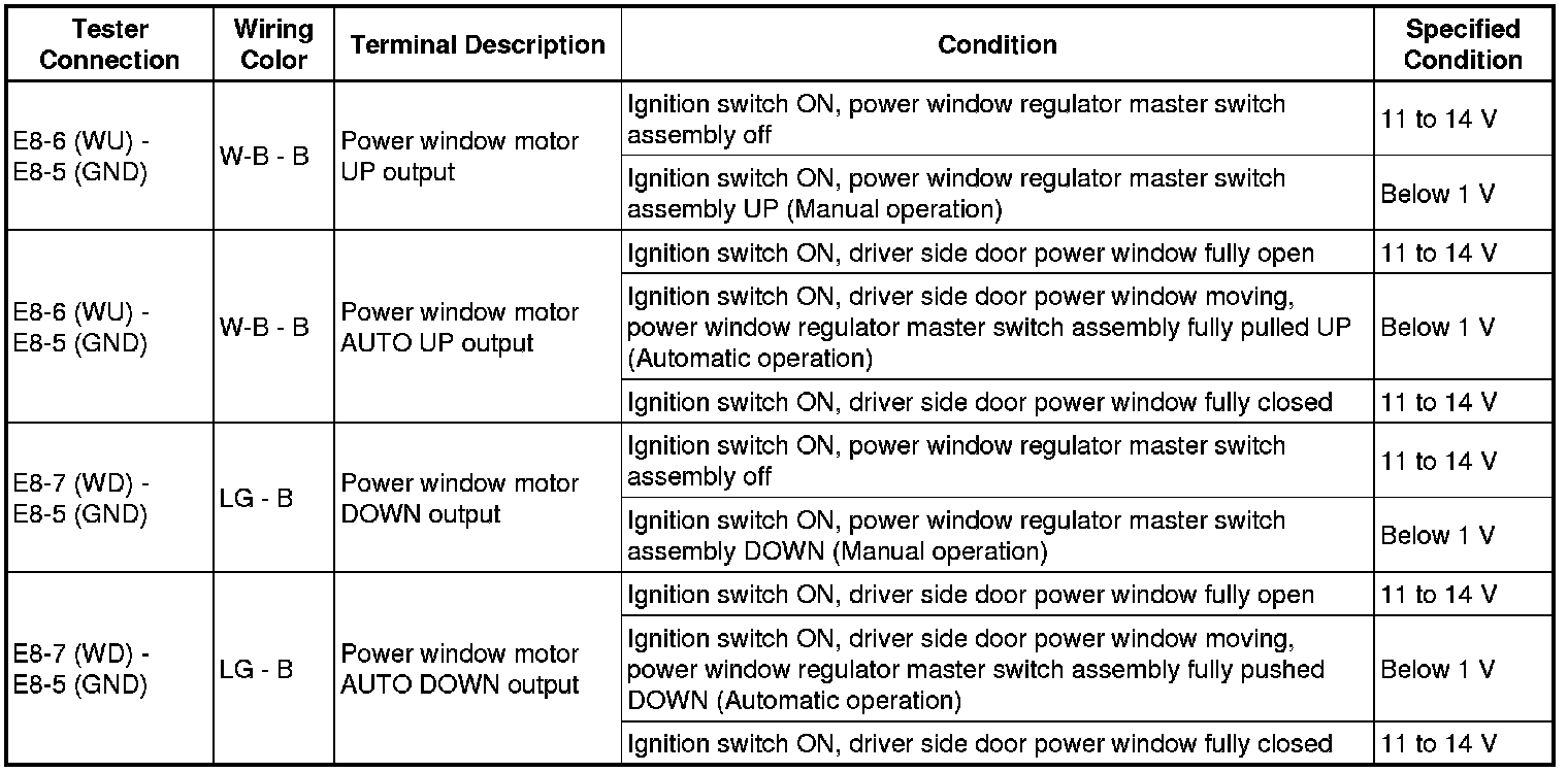
If the result is not as specified, the power window regulator master switch assembly may have a malfunction.
2. CHECK POWER WINDOW REGULATOR SWITCH ASSEMBLY
(a) Disconnect the F6 power window regulator switch assembly connector.

(b) Measure the voltage according to the value(s) in the table below.
HINT
Measure the values on the wire harness side with the connector disconnected.
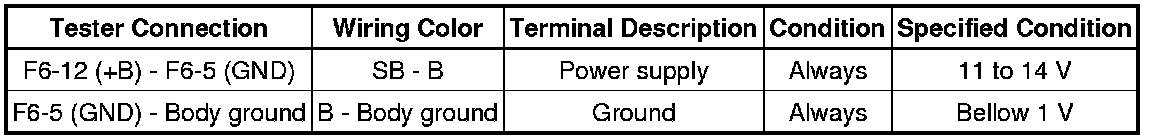
If the result is not as specified, there may be a malfunction in the wire harness.
(c) Reconnect the F6 power window regulator switch assembly connector.
(d) Measure the voltage according to the value(s) in the table below.
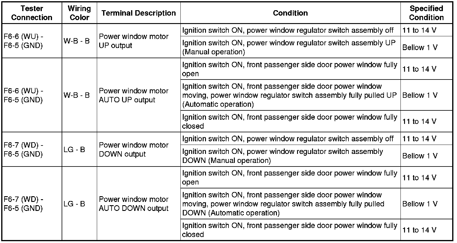
If the result is not as specified, the power window regulator switch assembly may have a malfunction.
3. CHECK POWER WINDOW REGULATOR MOTOR ASSEMBLY
(a) Disconnect the E5 power window regulator motor assembly (for driver side) connector.

(b) Measure the voltage and resistance according to the value(s) in the table below.
HINT
Measure the values on the wire harness side with the connector disconnected.
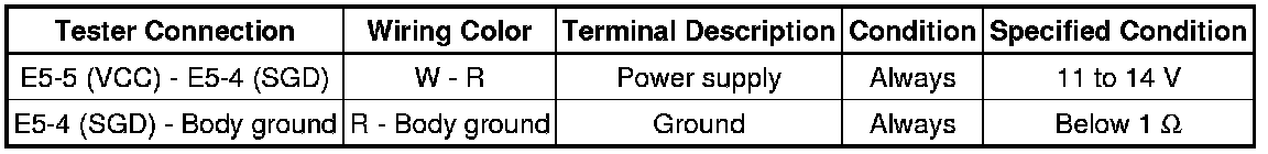
If the result is not as specified, there may be a malfunction in the wire harness.
(c) Reconnect the E5 power window regulator motor assembly (for driver side) connector.
(d) Measure the voltage according to the value(s) in the table below.
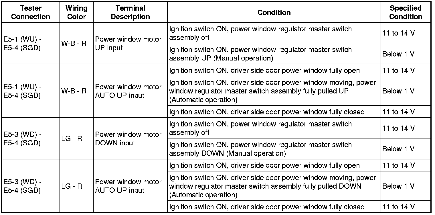
If the result is not as specified, the power window regulator motor assembly (for driver side) may have a malfunction.
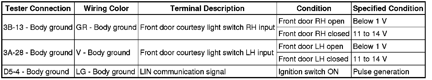
4. CHECK MAIN BODY ECU (NETWORK GATEWAY ECU) AND INSTRUMENT PANEL JUNCTION BLOCK ASSEMBLY
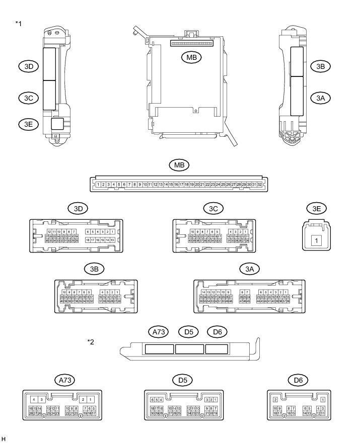
Text in illustration

(a) Remove the main body ECU (network gateway ECU) from the instrument panel junction block assembly.
(b) Measure the resistance and voltage according to the value(s) in the table below.
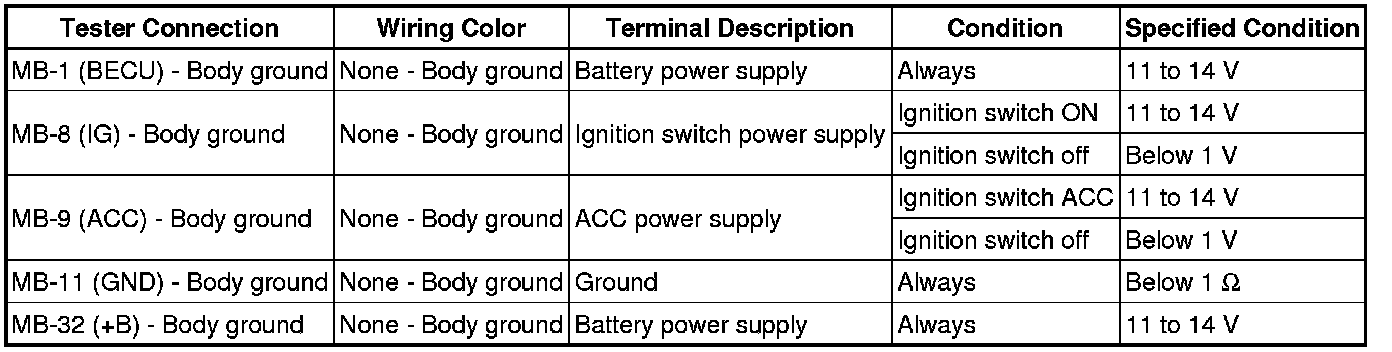
* If the result is not as specified, there may be a malfunction on the wire harness side.
(c) Reinstall the main body ECU (network gateway ECU).
(d) Measure the voltage of the wire harness side connectors.
If the result is not as specified, the main body ECU (network gateway ECU) or instrument panel junction block assembly may have a malfunction.