Reassembly
3UR-FE ENGINE MECHANICAL: ENGINE UNIT: REASSEMBLY
REASSEMBLY
1. INSTALL STUD BOLT

(a) Install the timing chain cover stud bolt.
(1) Using an E10 "TORX" socket wrench, install the 2 stud bolts as shown in the illustration.
Torque: 20 Nm (204 kgf-cm, 16 ft-lbf)

(b) Install the oil pan stud bolt.
(1) Using an E6 and E7 "TORX" socket wrench, install the 3 stud bolts as shown in the illustration.
- Stud bolt A
Torque: 5.0 Nm (51 kgf-cm, 44 in-lbf)
- Stud bolt B
Torque: 9.0 Nm (92 kgf-cm, 80 in-lbf)

2. INSTALL RING PIN
(a) Using a plastic-faced hammer, tap in new ring pins to the timing chain cover.
Standard Protrusion:

3. INSTALL ENGINE REAR OIL SEAL
(a) Apply MP grease to the lip of a new oil seal.

(b) Using SST, tap in the oil seal until its surface is flush with the oil seal retainer edge.
SST: 09223-15030
SST: 09950-70010
09951-07100
Standard depth:
0 to 1.0 mm (0 to 0.0394 in.)
NOTICE:
- Keep the lip free from foreign matter.
- Do not tap on the oil seal at an angle.

4. INSTALL OIL DRAIN PIPE SUB-ASSEMBLY
(a) Apply a light coat of engine oil to a new O-ring.
(b) Install the O-ring to the drain pipe.
(c) Install the oil drain pipe with the bolt.
Torque: 10 Nm (102 kgf-cm, 7 ft-lbf)
5. INSTALL ENGINE REAR OIL SEAL RETAINER

(a) Apply seal packing in a continuous line as shown in the illustration.
Seal packing:
Toyota Genuine Seal Packing Black, Three Bond 1207B or equivalent
Seal diameter:
2.0 to 3.0 mm (0.0787 to 0.118 in.)
Application position from inside edge of retainer:
3.5 mm (0.138 in.)
NOTICE:
- Remove any oil from the contact surface.
- Install the oil pan within 3 minutes and tighten the bolts and nuts within 15 minutes after applying seal packing.

(b) Install the oil seal retainer with the 6 bolts.
Torque: 10 Nm (102 kgf-cm, 7 ft-lbf)
NOTICE:
- Do not start the engine for at least 2 hours after installing.
- When installing the oil seal retainer, make sure the lip of the oil seal is not damaged.
- When installing the oil seal retainer, make sure the lip of the oil seal is not folded incorrectly.

6. INSTALL OIL STRAINER SUB-ASSEMBLY
(a) Apply a light coat of engine oil to a new O-ring.
(b) Install the O-ring to the oil strainer.
(c) Install the oil strainer with the 2 bolts.
Torque: 10 Nm (102 kgf-cm, 7 ft-lbf)
NOTE: Make sure the O-ring is not twisted or damaged.

7. INSTALL NO. 1 OIL PAN BAFFLE PLATE
(a) Install the baffle plate with the 7 bolts.
Torque: 10 Nm (102 kgf-cm, 7 ft-lbf)
8. INSTALL OIL PAN SUB-ASSEMBLY

(a) Apply seal packing in a continuous line as shown in the illustration.
Seal packing:
Toyota Genuine Seal Packing Black, Three Bond 1207B or equivalent
Standard seal diameter:
3.0 to 4.0 mm (0.118 to 0.157 in.)
NOTICE:
- Remove any oil from the contact surface.
- Install the oil pan within 3 minutes and tighten the bolts and nuts within 15 minutes after applying seal packing.
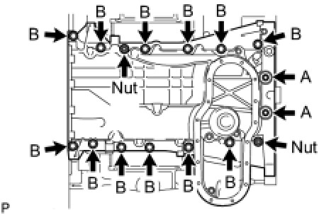
(b) Install the oil pan with the 14 bolts and 2 nuts.
- Bolt A
Torque: 10 Nm (102 kgf-cm, 7 ft-lbf)
- Bolt B
Torque: 35 Nm (357 kgf-cm, 26 ft-lbf)
- Nut
Torque: 35 Nm (357 kgf-cm, 26 ft-lbf)
NOTE: Do not start the engine for at least 2 hours after installing.
9. INSTALL NO. 2 OIL PAN SUB-ASSEMBLY

(a) Apply seal packing in a continuous line as shown in the illustration.
Seal packing:
Toyota Genuine Seal Packing Black, Three Bond 1207B or equivalent
Standard seal diameter:
3.0 to 4.0 mm (0.118 to 0.156 in.)
NOTICE:
- Remove any oil from the contact surface.
- Install the oil pan within 3 minutes and tighten the bolts and nuts within 15 minutes after applying seal packing.
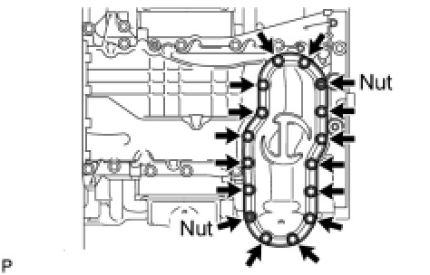
(b) Install the oil pan with the 14 bolts and 2 nuts.
Torque: 10 Nm (102 kgf-cm, 7 ft-lbf)
NOTE: Do not start the engine for at least 2 hours after installing.
10. INSTALL NO. 1 HEAT EXCHANGER COVER

(a) Apply seal packing in a continuous line as shown in the illustration.
Seal packing:
Toyota Genuine Seal Packing 1282B, Three Bond 1282B or equivalent
Standard seal diameter:
3.0 to 4.0 mm (0.118 to 0.157 in.)
NOTICE:
- Remove any oil from the contact surface.
- Install the No. 1 heat exchanger cover within 3 minutes and tighten the bolts and nuts within 15 minutes after applying seal packing.

(b) Install the heat exchanger cover with the 12 bolts and 2 nuts.
for bolt C - Torque: 10 Nm (102 kgf-cm, 7 ft-lbf)
except bolt C - Torque: 21 Nm (214 kgf-cm, 15 ft-lbf)
Standard Bolt:

NOTE: Do not start the engine for at least 2 hours after installing.

11. INSTALL VENTILATION PIPE GASKET
(a) Using SST, evenly tap in a new ventilation pipe gasket until its surface is flush with the lip of the ventilation pipe.
SST: 09950-60010
09951-00360
SST: 09950-70010
09951-07100
NOTICE:
- Do not tap the gasket at an angle.
- Do not tap the gasket excessively.

12. INSTALL CYLINDER BLOCK WATER JACKET SPACER
(a) Install the 2 water jacket spacers as shown in the illustration.
NOTICE:
- Face the cutouts indicated by the arrows in illustration away from the engine.
- Face the "up mark" as shown in the illustration.
13. INSTALL CYLINDER HEAD GASKET Installation
14. INSTALL CYLINDER HEAD SUB-ASSEMBLY Installation
15. INSTALL NO. 2 CYLINDER HEAD GASKET Installation
16. INSTALL CYLINDER HEAD LH Installation
17. INSTALL VALVE STEM CAP Installation
18. INSTALL VALVE LASH ADJUSTER ASSEMBLY Installation
19. INSTALL NO. 1 VALVE ROCKER ARM SUB-ASSEMBLY Installation
20. INSTALL CAMSHAFTS (for Bank 2) Installation
21. INSTALL CAMSHAFT HOUSING SUB-ASSEMBLY RH Installation
22. INSTALL CAMSHAFTS (for Bank 1) Installation
23. INSTALL CAMSHAFT HOUSING SUB-ASSEMBLY LH Installation

24. INSTALL CRANKSHAFT TIMING GEAR KEY
(a) Install the timing gear key.
HINT: The other timing gear key will be installed at a later step.
25. INSTALL NO. 2 CHAIN TENSIONER ASSEMBLY Installation
26. INSTALL CHAIN SUB-ASSEMBLY (for RH Side) Installation
27. INSTALL NO. 1 CHAIN VIBRATION DAMPER (for RH Side) Installation
28. INSTALL CHAIN TENSIONER SLIPPER (for RH Side) Installation
29. INSTALL NO. 1 CHAIN TENSIONER ASSEMBLY (for RH Side) Installation
30. INSTALL NO. 3 CHAIN TENSIONER ASSEMBLY Installation
31. INSTALL CHAIN SUB-ASSEMBLY (for LH Side) Installation
32. INSTALL CHAIN TENSIONER SLIPPER (for LH Side) Installation
33. INSTALL NO. 1 CHAIN TENSIONER ASSEMBLY (for LH Side) Installation
34. INSTALL NO. 1 CHAIN VIBRATION DAMPER (for LH Side) Installation
35. TIGHTEN CAMSHAFT TIMING GEAR ASSEMBLY (for LH Side) Installation
36. TIGHTEN CAMSHAFT TIMING GEAR ASSEMBLY (for RH Side) Installation
37. CHECK NO. 1 CYLINDER TO TDC / COMPRESSION Installation
38. INSTALL INLET WATER PIPE Installation
39. INSTALL TIMING CHAIN OR BELT COVER SUB-ASSEMBLY Installation
40. INSTALL WATER PUMP ASSEMBLY Installation
41. INSTALL TIMING GEAR CASE OR TIMING CHAIN CASE OIL SEAL

(a) Apply MP grease to the lip of a new oil seal.
(b) Using SST and a hammer, tap in the oil seal to a depth between 0 to 1.0 mm (0 to 0.0394 in.) from the timing chain cover edge.
SST: 09223-22010
SST: 09506-35010
NOTICE:
- Keep the lip free from foreign matter.
- Do not tap oil seal at an angle.
42. INSTALL CRANKSHAFT TIMING GEAR KEY

(a) Install the crankshaft timing gear key to the crankshaft.
43. INSTALL SPARK PLUG TUBE GASKET

(a) Using a cutter knife, cut off the seal part of the removed gasket.

(b) Using the removed gasket and a hammer, tap in a new gasket until it stops.
HINT: If the removed gasket does not fit on the new one, correct the removed one with pliers.
(c) Apply a light coat of MP grease to the gasket lip.
(d) Return the 4 ventilation baffle plate claws to the original positions.
44. INSTALL OIL CONTROL VALVE FILTER LH

(a) Install the valve filter in the cylinder head cover.
(b) Install a new gasket and the cylinder head cover spacer with the 3 bolts.
Torque: 10 Nm (102 kgf-cm, 7 ft-lbf)
45. INSTALL OIL CONTROL VALVE FILTER RH

(a) Install the valve filter in the cylinder head cover.
(b) Install a new gasket and the cylinder head cover spacer with the 3 bolts.
Torque: 10 Nm (102 kgf-cm, 7 ft-lbf)
46. INSTALL CYLINDER HEAD COVER SUB-ASSEMBLY LH Installation
47. INSTALL CYLINDER HEAD COVER SUB-ASSEMBLY Installation
48. INSTALL CAMSHAFT TIMING OIL CONTROL VALVE ASSEMBLY LH

(a) Apply a light coat of engine oil to 2 new O-rings.
(b) Install the 2 O-rings to the 2 oil control valves.
(c) Install the 2 oil control valves with the 2 bolts.
Torque: 10 Nm (102 kgf-cm, 7 ft-lbf)
49. INSTALL CAMSHAFT TIMING OIL CONTROL VALVE ASSEMBLY RH

(a) Apply a light coat of engine oil to 2 new O-rings.
(b) Install the 2 O-rings to the 2 oil control valves.
(c) Install the 2 oil control valves with the 2 bolts.
Torque: 10 Nm (102 kgf-cm, 7 ft-lbf)

50. INSTALL CRANKSHAFT POSITION SENSOR
(a) Install the crankshaft position sensor with the bolt.
Torque: 10 Nm (102 kgf-cm, 7 ft-lbf)

51. INSTALL CRANK POSITION SENSOR PROTECTOR
(a) Install the sensor protector with the 2 bolts.
Torque: 10 Nm (102 kgf-cm, 7 ft-lbf)

52. INSTALL CAMSHAFT POSITION SENSOR
(a) Install the camshaft position sensor with the bolt.
Torque: 10 Nm (102 kgf-cm, 7 ft-lbf)
53. INSTALL VVT SENSOR (for Bank 1)

(a) Install the 2 VVT sensors with the 2 bolts.
Torque: 10 Nm (102 kgf-cm, 7 ft-lbf)
54. INSTALL VVT SENSOR (for Bank 2)

(a) Install the 2 VVT sensors with the 2 bolts.
Torque: 10 Nm (102 kgf-cm, 7 ft-lbf)
55. INSTALL OIL FILLER CAP HOUSING

(a) Align the protrusion of a new gasket with the cutout of the oil filler cap housing, and install the gasket to the housing.

(b) Install the cap housing with the 2 bolts.
Torque: 10 Nm (102 kgf-cm, 7 ft-lbf)
56. INSTALL OIL FILLER CAP SUB-ASSEMBLY
57. INSTALL CRANKSHAFT PULLEY Installation
58. INSTALL OIL FILTER BRACKET Installation
59. INSTALL NO. 1 OIL COOLER BRACKET (w/ Oil Cooler) Installation
60. INSTALL OIL FILTER ELEMENT Replacement
61. INSTALL OIL FILTER CAP ASSEMBLY Replacement
62. INSTALL OIL FILTER DRAIN PLUG Replacement