Speaker Circuit
NAVIGATION: NAVIGATION SYSTEM (w/o USB Audio System): Speaker Circuit
- Speaker Circuit
DESCRIPTION
The navigation receiver assembly sends sound signals to the speaker.
WIRING DIAGRAM

INSPECTION PROCEDURE
PROCEDURE
1. CHECK SPEAKER
(a) Check the malfunctioning speakers.
Result

*: except Regular Cab
B -- INSPECT REAR NO. 1 SPEAKER ASSEMBLY
A -- Continue to next step.
2. CHECK FRONT SIDE SPEAKER
(a) Check the malfunctioning speakers.
Result

B -- INSPECT FRONT NO. 1 SPEAKER ASSEMBLY
A -- Continue to next step.
3. INSPECT FRONT NO. 2 SPEAKER ASSEMBLY
(a) Disconnect the K11*1 and/or K13*2 front No. 2 speaker assembly connector.
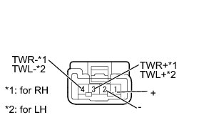
*1: for RH
*2: for LH
(b) Measure the resistance according to the value(s) in the table below.
Standard Resistance:
for RH
for LH


Result

D -- REPLACE FRONT NO. 2 SPEAKER ASSEMBLY Removal
C -- REPLACE FRONT NO. 2 SPEAKER ASSEMBLY Removal
B -- REPLACE FRONT NO. 2 SPEAKER ASSEMBLY Removal
A -- Continue to next step.
4. CHECK HARNESS AND CONNECTOR (NAVIGATION RECEIVER - FRONT NO. 2 SPEAKER)
(a) Disconnect the K30 navigation receiver assembly connector.

(b) Disconnect the K11*1 and/or K13*2 front No. 2 speaker assembly connector.
*1: for RH
*2: for LH
(c) Measure the resistance according to the value(s) in the table below.
Standard Resistance:
for RH
for LH


Result

C -- REPAIR OR REPLACE HARNESS OR CONNECTOR
B -- REPLACE NAVIGATION RECEIVER ASSEMBLY Removal
A -- REPLACE NAVIGATION RECEIVER ASSEMBLY Removal
5. INSPECT FRONT NO. 1 SPEAKER ASSEMBLY
(a) Disconnect the M8*1 and/or N10*2 front No. 1 speaker assembly connector.
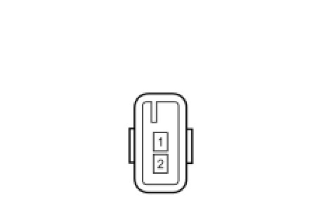
*1: for RH
*2: for LH
(b) Measure the resistance according to the value(s) in the table below.
Standard Resistance:

Result

D -- REPLACE FRONT NO. 1 SPEAKER ASSEMBLY Removal
C -- REPLACE FRONT NO. 1 SPEAKER ASSEMBLY Removal
B -- REPLACE FRONT NO. 1 SPEAKER ASSEMBLY Removal
A -- Continue to next step.
6. CHECK HARNESS AND CONNECTOR (FRONT NO. 2 SPEAKER - FRONT NO. 1 SPEAKER)
*1: for RH
*2: for LH
(a) Disconnect the K11*1 and/or K13*2 front No. 2 speaker assembly connector.

(b) Disconnect the M8*1 and/or N10*2 front No. 1 speaker assembly connector.
(c) Measure the resistance according to the value(s) in the table below.
Standard Resistance:
for RH
for LH


Result

C -- REPAIR OR REPLACE HARNESS OR CONNECTOR
B -- REPLACE NAVIGATION RECEIVER ASSEMBLY Removal
A -- REPLACE NAVIGATION RECEIVER ASSEMBLY Removal
7. INSPECT REAR NO. 1 SPEAKER ASSEMBLY
(a) Disconnect the O1*1 and O7*2 rear No. 1 speaker assembly connectors.
*1: for RH
*2: for LH
(b) Measure the resistance according to the value(s) in the table below.
Standard Resistance:

Result

C -- REPLACE REAR NO. 1 SPEAKER ASSEMBLY Removal
B -- REPLACE REAR NO. 1 SPEAKER ASSEMBLY Removal
A -- Continue to next step.
8. CHECK HARNESS AND CONNECTOR (NAVIGATION RECEIVER - REAR NO. 1 SPEAKER)
(a) Disconnect the K31 navigation receiver assembly connector.

(b) Disconnect the O1*1 and/or O7*2 rear No. 1 speaker assembly connector.
*1: for RH
*2: for LH
(c) Measure the resistance according to the value(s) in the table below.
Standard Resistance:
for RH
for LH


Result

C -- REPAIR OR REPLACE HARNESS OR CONNECTOR
B -- REPLACE NAVIGATION RECEIVER ASSEMBLY Removal
A -- REPLACE NAVIGATION RECEIVER ASSEMBLY Removal