Bus Buffer ECU Communication Stop Mode (from 08/2011)
CAN COMMUNICATION: CAN COMMUNICATION SYSTEM: Bus Buffer ECU Communication Stop Mode
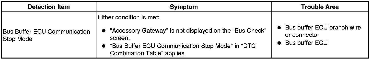
- Bus Buffer ECU Communication Stop Mode
DESCRIPTION
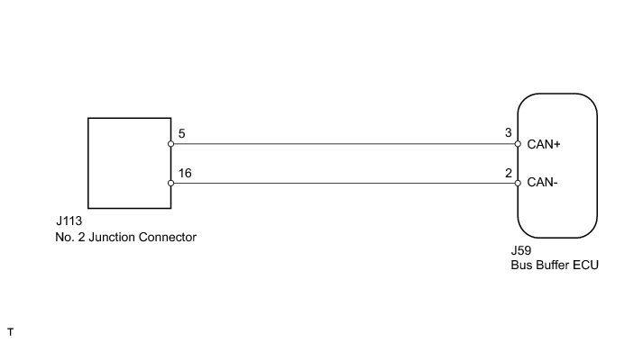
WIRING DIAGRAM
INSPECTION PROCEDURE
HINT
Operating the ignition switch, any switches or any doors triggers related ECU and sensor communication with the CAN, which causes resistance variation.
PROCEDURE
1. PRECAUTION
NOTICE:
After turning the ignition switch off, waiting time may be required before disconnecting the cable from the battery terminal. Therefore, make sure to read the disconnecting the cable from the battery terminal notice before proceeding with work Service Precautions.
NEXT -- Continue to next step.
2. DISCONNECT CABLE FROM NEGATIVE BATTERY TERMINAL
(a) Disconnect the cable from the negative (-) battery terminal before measuring the resistances of the main wire and the branch wire.
CAUTION:
Wait at least 90 seconds after disconnecting the cable from the negative (-) battery terminal to prevent airbag and seat belt pretensioner activation.
NEXT -- Continue to next step.
3. CHECK FOR OPEN IN CAN BUS WIRE (BUS BUFFER ECU BRANCH WIRE)
(a) Disconnect the J59 bus buffer ECU connector.
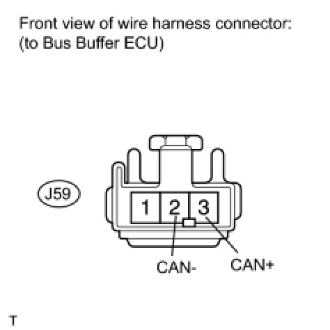
(b) Measure the resistance according to the value(s) in the table below.
Standard resistance:
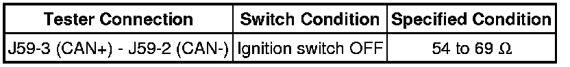
NG -- REPAIR OR REPLACE BUS BUFFER ECU BRANCH WIRE OR CONNECTOR (CAN+, CAN-)
OK -- REPLACE BUS BUFFER ECU