Door Key Lock / Unlock Switch Circuit
DOOR LOCK: POWER DOOR LOCK CONTROL SYSTEM: Door Key Lock / Unlock Switch Circuit
Door Key Lock / Unlock Switch Circuit
DESCRIPTION
The door lock and unlock switch is built into the door lock assembly.
This switch is ON when the door key is in the unlock position and OFF when the door key is in the lock position. It is used as one of the operating conditions for the key confinement prevention function.
WIRING DIAGRAM
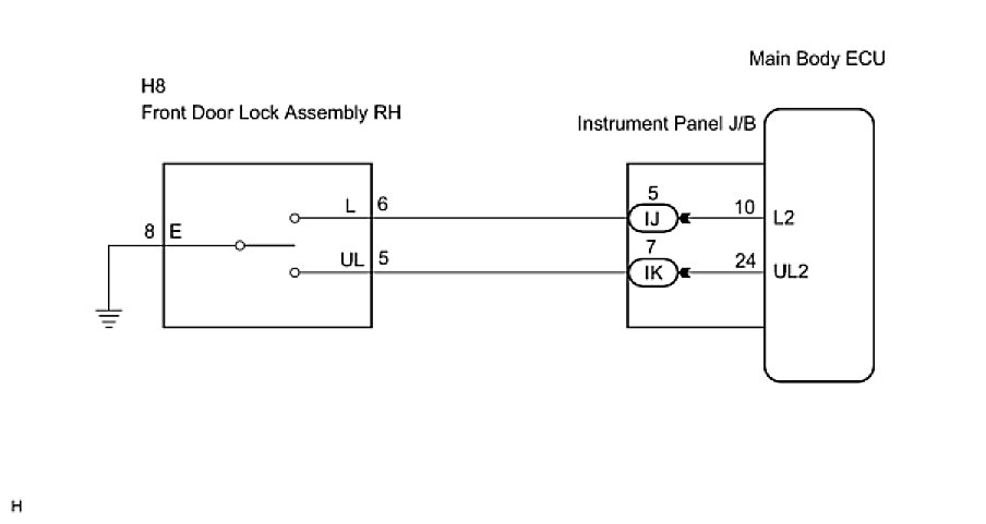
INSPECTION PROCEDURE
PROCEDURE
1. INSPECT FRONT DOOR LOCK ASSEMBLY RH (DOOR KEY LOCK AND UNLOCK SWITCH)
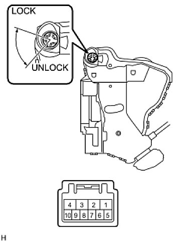
(a) Remove the front door lock assembly RH.
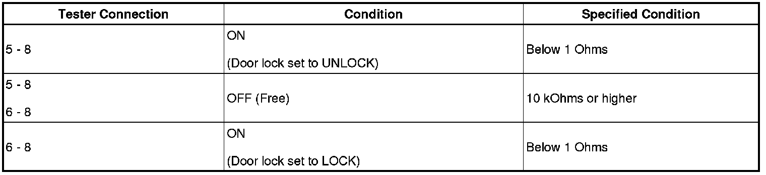
(b) Measure the resistance according to the value(s) in the table below.
Standard resistance:
NG -- REPLACE FRONT DOOR LOCK ASSEMBLY LH
OK -- Continue to next step.
2. CHECK WIRE HARNESS (FRONT DOOR LOCK RH - MAIN BODY ECU (INSTRUMENT PANEL J/B))
(a) Disconnect the IJ J/B connector.
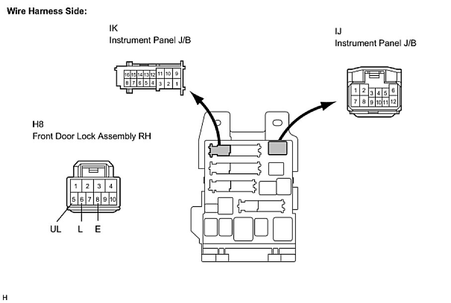
(b) Measure the resistance according to the value(s) in the table below.
Standard resistance:

NG -- REPAIR OR REPLACE HARNESS OR CONNECTOR
OK -- PROCEED TO NEXT CIRCUIT INSPECTION SHOWN IN PROBLEM SYMPTOMS TABLE