Security Indicator Light Circuit
ENGINE IMMOBILISER: ENGINE IMMOBILISER SYSTEM (w/o Smart Key System): Security Indicator Light Circuit
- Security Indicator Light Circuit
DESCRIPTION
When the transponder key is registered, the transponder key ECU assembly outputs the key registration condition by lighting up, blinking or turning off the security indicator.
WIRING DIAGRAM
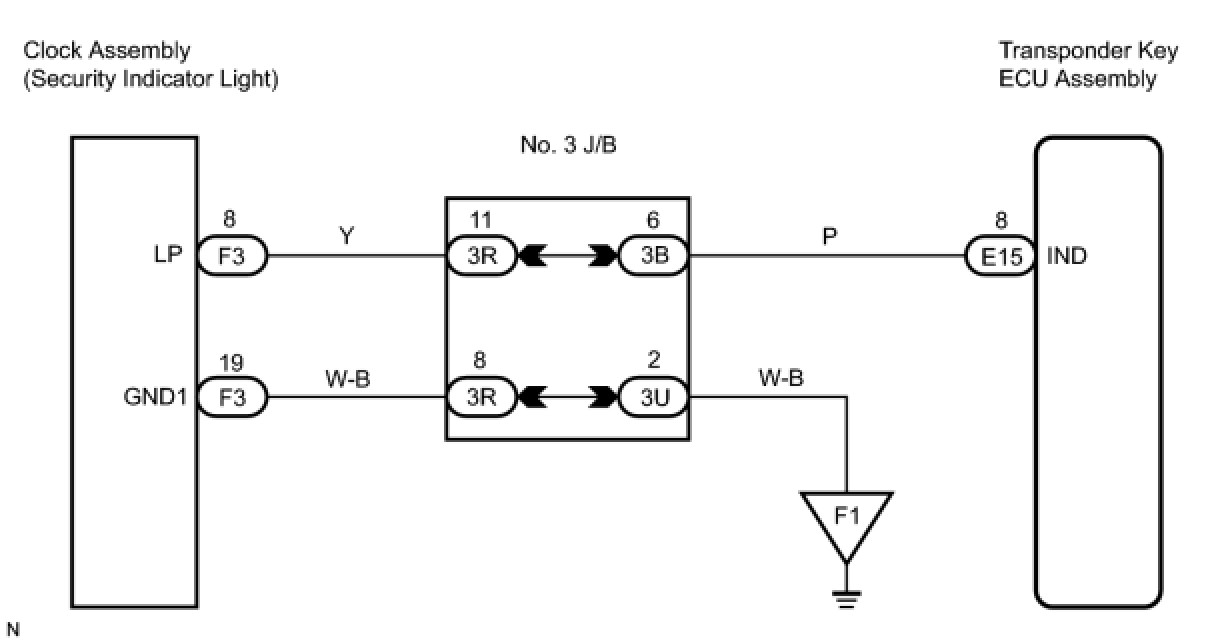
INSPECTION PROCEDURE
NOTICE:
If the transponder key ECU assembly is replaced, register the key and ECU communication ID Engine Immobiliser System (W/O Smart Key System).
PROCEDURE
1. PERFORM ACTIVE TEST USING TECHSTREAM
(a) Connect Techstream to the DLC3.
(b) Turn the ignition switch to the ON position.
(c) Turn the tester on.
(d) Enter the following menus: Body Electrical / Immobiliser / Active Test.
(e) Perform the Active Test according to the display on the tester.
Immobiliser:

OK:
Security indicator turns on and off.
OK -- PROCEED TO NEXT CIRCUIT INSPECTION SHOWN IN PROBLEM SYMPTOMS TABLE
NG -- Continue to next step.
2. CHECK HARNESS AND CONNECTOR (TRANSPONDER KEY ECU - SECURITY INDICATOR LIGHT)
(a) Disconnect the E15 ECU and F3 combination meter connectors.
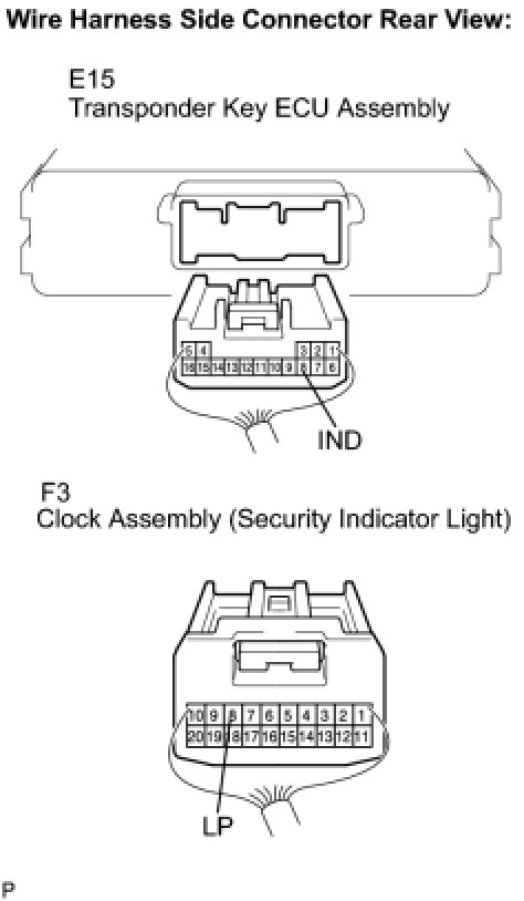
(b) Measure the resistance according to the value(s) in the table below.
Standard resistance:
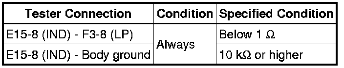
NG -- REPAIR OR REPLACE HARNESS OR CONNECTOR
OK -- Continue to next step.
3. CHECK HARNESS AND CONNECTOR (SECURITY INDICATOR LIGHT - BODY GROUND)
(a) Measure the resistance according to the value(s) in the table below.
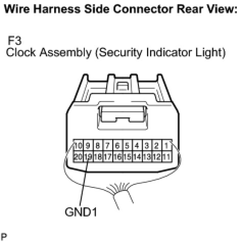
Standard resistance:
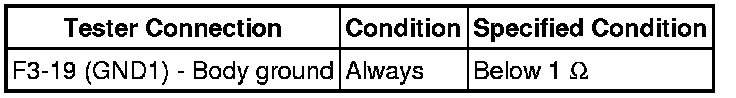
NG -- REPAIR OR REPLACE HARNESS OR CONNECTOR
OK -- Continue to next step.
4. INSPECT TRANSPONDER KEY ECU ASSEMBLY
(a) Reconnect the E15 ECU and F3 combination meter connectors.
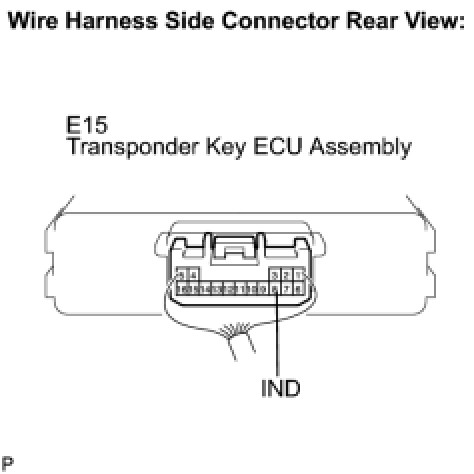
(b) Measure the voltage according to the value(s) in the table below.
Standard voltage:
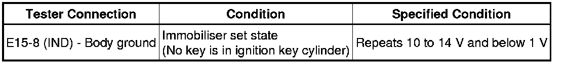
NG -- REPLACE TRANSPONDER KEY ECU ASSEMBLY
OK -- REPLACE CLOCK ASSEMBLY