Room Oscillator Does Not Recognize Key
THEFT DETERRENT / KEYLESS ENTRY: SMART KEY SYSTEM (for Entry Function): Room Oscillator does not Recognize Key
- Room Oscillator does not Recognize Key
DESCRIPTION
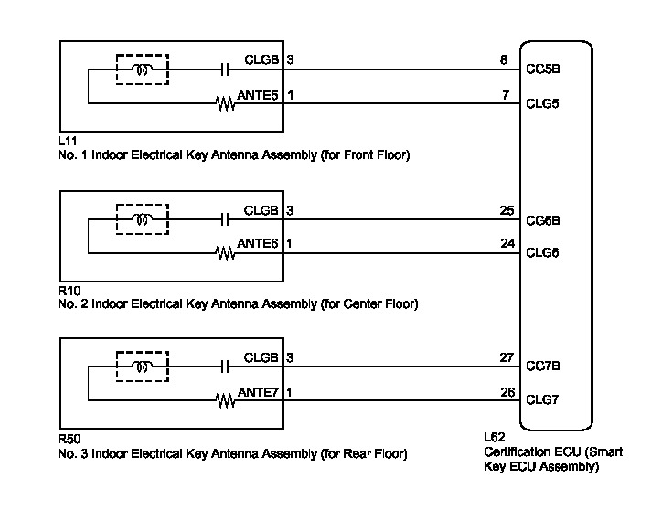
If the room antenna does not recognize a key, one of the following may be the cause: 1) communication between the No. 1 indoor electrical key antenna assembly (for front floor) and key cannot be performed; 2) communication between the No. 2 indoor electrical key antenna assembly (for center floor) and key cannot be performed; or 3) communication between the No. 3 indoor electrical key antenna assembly (for rear floor) and key cannot be performed.
WIRING DIAGRAM
INSPECTION PROCEDURE
NOTICE:
* The smart key system (for entry function) uses a LIN communication system and CAN communication system. Inspect the communication function by following How to Proceed with Troubleshooting How To Proceed With Troubleshooting. Troubleshoot the smart key system (for entry function) after confirming that the communication system is functioning properly.
* When using the Techstream with the power switch off to troubleshoot:
Connect the Techstream to the DLC3, and turn a courtesy light switch on and off at 1.5-second intervals until communication between the Techstream and vehicle begins.
PROCEDURE
1. CHECK SMART KEY SYSTEM (for Entry Function)
(a) Check that entry lock and unlock functions can be operated at each door How To Proceed With Troubleshooting.
OK:
Entry lock and unlock functions operate normally.
NG -- GO TO OTHER PROBLEM (Proceed to Problem Symptoms Table) Problem Symptoms Table
OK -- Continue to next step.
2. CHECK SMART KEY SYSTEM (for Start Function)
(a) Remove the battery of the key How To Proceed With Troubleshooting.
(b) With the brake pedal depressed, touch the power switch while facing the logo side of the key to the power switch.

(c) When operating the power switch, check whether the power source mode changes.
OK:
Power source mode changes.
HINT
* When the key cannot be verified even though it is within the specified range, the hybrid vehicle control system start check can be performed by removing the transmitter battery from the key and holding the transmitter close to the power switch.
* When performing the check, if the power source mode changes, there is a problem with key certification inside the cabin.
NG -- GO TO SMART KEY SYSTEM (for Start Function) (Proceed to Power Source Mode does not Change to ON) Power Source Mode does not Change to ON (IG and ACC)
OK -- Continue to next step.
3. CHECK WAVE ENVIRONMENT
(a) Install the battery to the key Transmitter Battery.
(b) Bring the key near the No. 1 indoor electrical key antenna assembly (for front floor), and check that the hybrid vehicle control system can be started.
NOTICE:
If the key is brought within 0.2 m (0.656 ft.) of the No. 1 indoor electrical key antenna assembly (for front floor), communication is not possible.
(c) Bring the key near the No. 2 indoor electrical key antenna assembly (for center floor), and check that the hybrid vehicle control system can be started.
NOTICE:
If the key is brought within 0.2 m (0.656 ft.) of the No. 2 indoor electrical key antenna assembly (for center floor), communication is not possible.
(d) Bring the key near the No. 3 indoor electrical key antenna assembly (for rear floor), and check that the hybrid vehicle control system can be started*.
*: If the customize setting for Ignition Available Area is not set All, the hybrid vehicle control system will not start. Before performing this inspection, check that All has been selected Smart Key System (for Entry Function).
NOTICE:
If the key is brought within 0.2 m (0.656 ft.) of the No. 3 indoor electrical key antenna assembly (for rear floor), communication is not possible.
HINT
* When the key is brought near the indoor electrical key antenna, the possibility of wave interference decreases, and it can be determined if wave interference is causing the problem symptom.
* If the operation is normal, the possibility of wave interference is high. Also, added vehicle components may cause wave interference. If installed, remove them and perform the operation check.
OK:
The hybrid vehicle control system starts.
NG -- PERFORM KEY DIAGNOSTIC MODE INSPECTION
OK -- AFFECTED BY WAVE INTERFERENCE
4. PERFORM KEY DIAGNOSTIC MODE INSPECTION
(a) Diagnostic mode inspection (No. 1 indoor electrical key antenna assembly (for front floor))

(1) Connect the Techstream to the DLC3.
(2) Turn the power switch on (IG).
(3) Turn the Techstream on.
(4) Enter the following menus: Body Electrical / Smart Key / Utility / Key Communication Check / Overhead + Front Room.
(5) When the electrical key transmitter is in the position shown in the illustration, check that the wireless door lock buzzer sounds.
HINT
* Place the key on the driver or front passenger seat cushion.
* If the buzzer sounds, it can be determined that the No. 1 indoor electrical key antenna assemblies are operating normally.
(b) Diagnostic mode inspection (No. 2 indoor electrical key antenna assembly (for center floor))

(1) Connect the Techstream to the DLC3.
(2) Turn the power switch on (IG).
(3) Turn the Techstream on.
(4) Enter the following menus: Body Electrical / Smart Key / Utility / Key Communication Check / Overhead + Rear Room.
(5) When the electrical key transmitter is in the position shown in the illustration, check that the wireless door lock buzzer sounds.
HINT
* Place the key on the rear seat cushion.
* If the buzzer sounds, it can be determined that the No. 2 indoor electrical key antenna assemblies are operating normally.
(c) Diagnostic mode inspection (No. 3 indoor electrical key antenna assembly (for rear floor))

(1) Connect the Techstream to the DLC3.
(2) Turn the power switch on (IG).
(3) Turn the Techstream on.
(4) Enter the following menus: Body Electrical / Smart Key / Utility / Key Communication Check / Overhead + Back Door (inside).
(5) When the electrical key transmitter is in the position shown in the illustration, check that the wireless door lock buzzer sounds.
HINT
* Place the key on the luggage area.
* If the buzzer sounds, it can be determined that the No. 3 indoor electrical key antenna assemblies are operating normally.
Result:
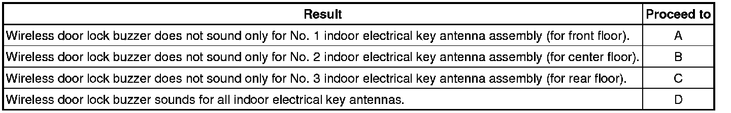
B -- CHECK HARNESS AND CONNECTOR 8CERTIFICATION ECU - NO. 2 INDOOR ELECTRICAL KEY ANTENNA ASSEMBLY)
C -- CHECK HARNESS AND CONNECTOR (CERTIFICATION ECU - NO. 3 INDOOR ELECTRICAL KEY ANTENNA ASSEMBLY)
D -- REPLACE CERTIFICATION ECU (SMART KEY ECU ASSEMBLY) Removal
A -- Continue to next step.
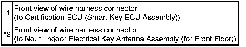
5. CHECK HARNESS AND CONNECTOR (CERTIFICATION ECU - NO. 1 INDOOR ELECTRICAL KEY ANTENNA ASSEMBLY)
(a) Disconnect the certification ECU (smart key ECU assembly) connector.
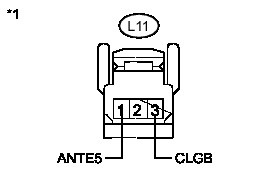
(b) Disconnect the No. 1 indoor electrical key antenna assembly (for front floor) connector.
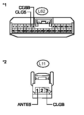
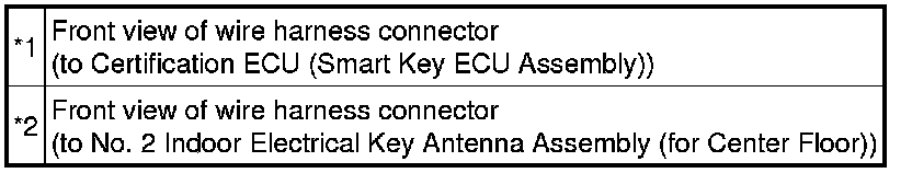
(c) Measure the resistance according to the value(s) in the table below.
Standard Resistance:
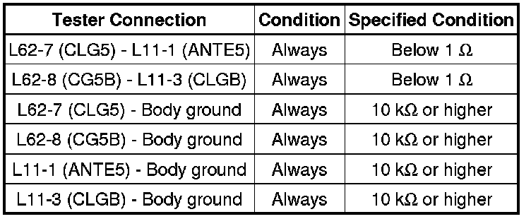
Text in Illustration
NG -- REPAIR OR REPLACE HARNESS OR CONNECTOR
OK -- Continue to next step.
6. INSPECT NO. 1 INDOOR ELECTRICAL KEY ANTENNA ASSEMBLY (for Front Floor (INPUT))
(a) Reconnect the certification ECU (smart key ECU assembly) connector.
(b) Check for pulses according to the value(s) in the table below.
Standard:
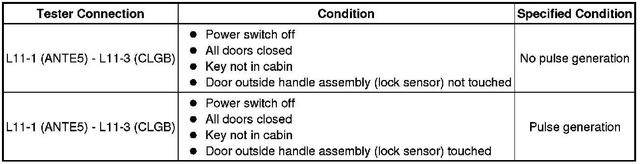
Text in Illustration
NG -- REPLACE CERTIFICATION ECU (SMART KEY ECU ASSEMBLY) Removal
OK -- Continue to next step.
7. REPLACE NO. 1 INDOOR ELECTRICAL KEY ANTENNA ASSEMBLY (for Front Floor)
(a) Replace the No. 1 indoor electrical key antenna assembly (for front floor Removal.
NEXT -- Continue to next step.
8. PERFORM KEY DIAGNOSTIC MODE INSPECTION (for Front Floor)
(a) Connect the Techstream to the DLC3.
(b) Turn the power switch on (IG).
(c) Turn the Techstream on.
(d) Enter the following menus: Body Electrical / Smart Key / Utility / Key Communication Check / Overhead + Front Room.
(e) When the electrical key transmitter is in the position shown in the illustration, check that the wireless door lock buzzer sounds.
OK:
Wireless door lock buzzer sounds.
HINT
* Place the key on the driver or front passenger seat cushion.
* If the buzzer sounds, it can be determined that the No. 1 indoor electrical key antenna assemblies are operating normally.
NG -- REPLACE CERTIFICATION ECU (SMART KEY ECU ASSEMBLY) Removal
OK -- END (NO. 1 INDOOR ELECTRICAL KEY ANTENNA ASSEMBLY WAS DEFECTIVE)
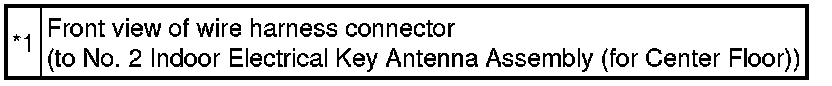
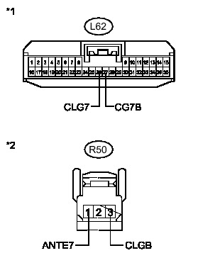
9. CHECK HARNESS AND CONNECTOR 8CERTIFICATION ECU - NO. 2 INDOOR ELECTRICAL KEY ANTENNA ASSEMBLY)
(a) Disconnect the certification ECU (smart key ECU assembly) connector.
(b) Disconnect the No. 2 indoor electrical key antenna assembly (for center floor) connector.
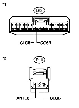
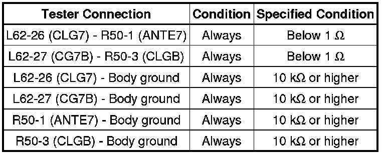
(c) Measure the resistance according to the value(s) in the table below.
Standard Resistance:
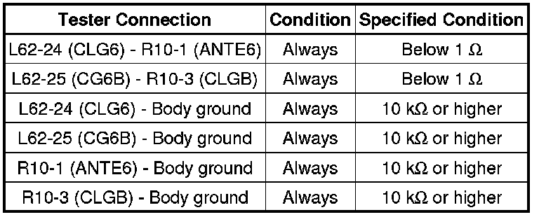
Text in Illustration
NG -- REPAIR OR REPLACE HARNESS OR CONNECTOR
OK -- Continue to next step.
10. INSPECT NO. 2 INDOOR ELECTRICAL KEY ANTENNA ASSEMBLY (for Center Floor (INPUT))
(a) Reconnect the certification ECU (smart key ECU assembly) connector.
(b) Check for pulses according to the value(s) in the table below.
Standard:
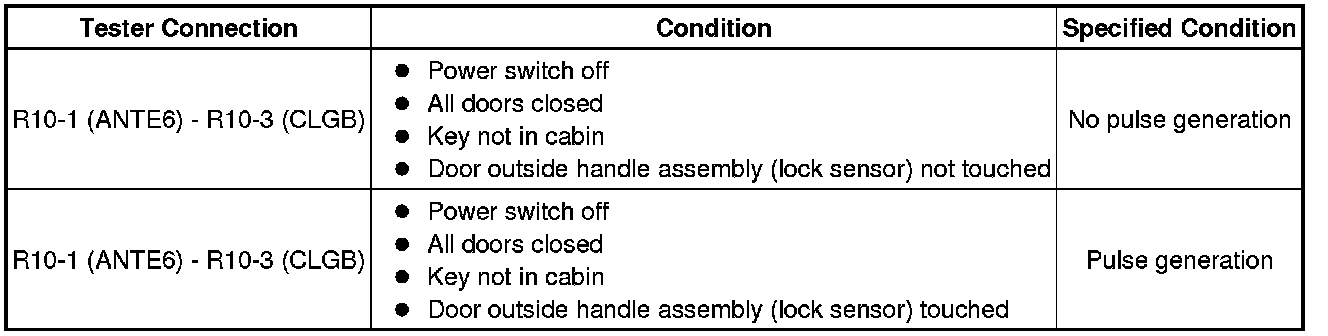
Text in Illustration
NG -- REPLACE CERTIFICATION ECU (SMART KEY ECU ASSEMBLY) Removal
OK -- Continue to next step.
11. REPLACE NO. 2 INDOOR ELECTRICAL KEY ANTENNA ASSEMBLY (for Center Floor)
(a) Replace the No. 2 indoor electrical key antenna assembly (for center floor) Removal.
NEXT -- Continue to next step.
12. PERFORM KEY DIAGNOSTIC MODE INSPECTION (for Center Floor)
(a) Connect the Techstream to the DLC3.
(b) Turn the power switch on (IG).
(c) Turn the Techstream on.
(d) Enter the following menus: Body Electrical / Smart Key / Utility / Key Communication Check / Overhead + Rear Room.
(e) When the electrical key transmitter is in the position shown in the illustration, check that the wireless door lock buzzer sounds.
OK:
Wireless door lock buzzer sounds.
HINT
* Place the key on the driver or front passenger seat cushion.
* If the buzzer sounds, it can be determined that the No. 2 indoor electrical key antenna assemblies are operating normally.
NG -- REPLACE CERTIFICATION ECU (SMART KEY ECU ASSEMBLY) Removal
OK -- END (NO. 2 INDOOR ELECTRICAL KEY ANTENNA ASSEMBLY WAS DEFECTIVE)
13. CHECK HARNESS AND CONNECTOR (CERTIFICATION ECU - NO. 3 INDOOR ELECTRICAL KEY ANTENNA ASSEMBLY)
(a) Disconnect the certification ECU (smart key ECU assembly) connector.
(b) Disconnect the No. 3 indoor electrical key antenna assembly (for rear floor) connector.
(c) Measure the resistance according to the value(s) in the table below.
Standard Resistance:
Text in Illustration

NG -- REPAIR OR REPLACE HARNESS OR CONNECTOR
OK -- Continue to next step.
14. INSPECT NO. 3 INDOOR ELECTRICAL KEY ANTENNA ASSEMBLY (for Rear Floor (INPUT))
(a) Reconnect the certification ECU (smart key ECU assembly) connector.
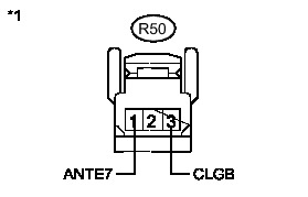
(b) Check for pulses according to the value(s) in the table below.
Standard:

Text in Illustration
NG -- REPLACE CERTIFICATION ECU (SMART KEY ECU ASSEMBLY) Removal
OK -- Continue to next step.
15. REPLACE NO. 3 INDOOR ELECTRICAL KEY ANTENNA ASSEMBLY (for Rear Floor)
(a) Replace the No. 3 indoor electrical key antenna assembly (for rear floor) Removal.
NEXT -- Continue to next step.
16. PERFORM KEY DIAGNOSTIC MODE INSPECTION (for Rear Floor)
(a) Connect the Techstream to the DLC3.
(b) Turn the power switch on (IG).
(c) Turn the Techstream on.
(d) Enter the following menus: Body Electrical / Smart Key / Utility / Key Communication Check / Overhead + Back Door (inside).
(e) When the electrical key transmitter is in the position shown in the illustration, check that the wireless door lock buzzer sounds.
OK:
Wireless door lock buzzer sounds.
HINT
* Place the key on the driver or front passenger seat cushion.
* If the buzzer sounds, it can be determined that the No. 3 indoor electrical key antenna assemblies are operating normally.
NG -- REPLACE CERTIFICATION ECU (SMART KEY ECU ASSEMBLY) Removal
OK -- END (NO. 3 INDOOR ELECTRICAL KEY ANTENNA ASSEMBLY WAS DEFECTIVE)