Pattern Select Switch EV/HV Mode Circuit
HYBRID / BATTERY CONTROL: HYBRID CONTROL SYSTEM: Pattern Select Switch EV/HV Mode Circuit
- Pattern Select Switch EV/HV Mode Circuit
DESCRIPTION
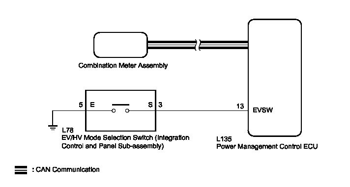
The EV drive mode signal is sent to the power management control ECU. This signal is then transmitted from the power management control ECU via CAN to the combination meter assembly to illuminate the EV mode indicator lamp.
WIRING DIAGRAM
INSPECTION PROCEDURE
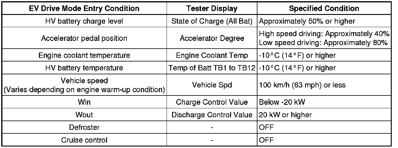
If any of the following conditions are not met, EV drive mode may not be turned on or the mode may be cancelled. (A buzzer sounds to indicate that the transition to EV drive mode is cancelled.)
PROCEDURE
1. ASK ABOUT VEHICLE CONDITION
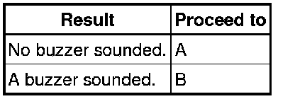
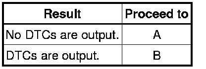
(a) Check if a buzzer sounded when attempting to enter EV drive mode.
Result:
HINT
If a buzzer sounds, one or more of the EV drive mode entry conditions have not been met. Check that all of the EV drive mode entry conditions have been met before pressing the EV/HV mode selection switch (integration control and panel sub-assembly).
B -- COMPLETED
A -- Continue to next step.
2. READ VALUE USING TECHSTREAM (CAN BUS CHECK)
(a) Connect the Techstream to the DLC3.
(b) Turn the power switch on (IG).
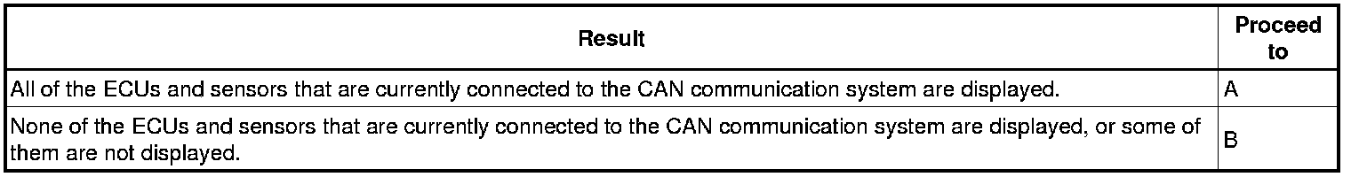
(c) Enter the following menus: System Select / CAN Bus Check.
Result:
(d) Turn the power switch off.
B -- GO TO CAN COMMUNICATION SYSTEM How to Proceed With Troubleshooting
A -- Continue to next step.
3. CHECK DTC OUTPUT (HEALTH CHECK)
(a) Connect the Techstream to the DLC3.
(b) Turn the power switch on (IG).
(c) Enter the following menus: System Select / Health Check.
(d) Check DTCs.
Result
(e) Turn the power switch off.
B -- GO TO DTC CHART
A -- Continue to next step.
4. PERFORM ACTIVE TEST USING TECHSTREAM (INDICAT. EV MODE)
(a) Connect the Techstream to the DLC3.
(b) Turn the power switch on (READY).
(c) Enter the following menus: Body Electrical / Combination Meter / Active Test / Indicat. EV Mode.
(d) Perform the "Indicat. EV Mode" Active Test.
OK:
The EV mode indicator lamp comes on or blinks.
(e) Turn the power switch off.
NG -- REPLACE NO. 2 METER CIRCUIT PLATE Components
OK -- Continue to next step.
5. READ VALUE USING TECHSTREAM (EV REQUEST, EV SWITCH)
(a) Connect the Techstream to the DLC3.
(b) Turn the power switch on (IG).
(c) Enter the following menus: Powertrain / Hybrid Control / Data List / EV request, EV Switch.
(d) Read the value displayed on the Techstream.
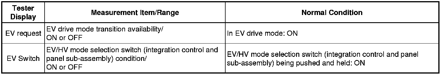
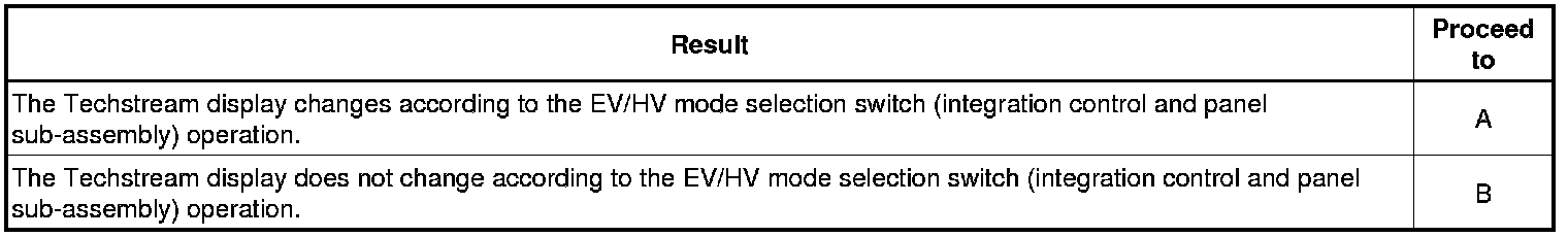
Result:
(e) Turn the power switch off.
B -- CHECK EV/HV MODE SELECTION SWITCH (INTEGRATION CONTROL AND PANEL SUB-ASSEMBLY)
A -- CHECK FOR INTERMITTENT PROBLEMS Check for Intermittent Problems
6. CHECK EV/HV MODE SELECTION SWITCH (INTEGRATION CONTROL AND PANEL SUB-ASSEMBLY)
(a) Remove the EV/HV mode selection switch (integration control and panel sub-assembly) Components.
(b) Measure the resistance according to the value(s) in the table below.
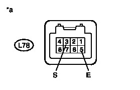
Standard Resistance:
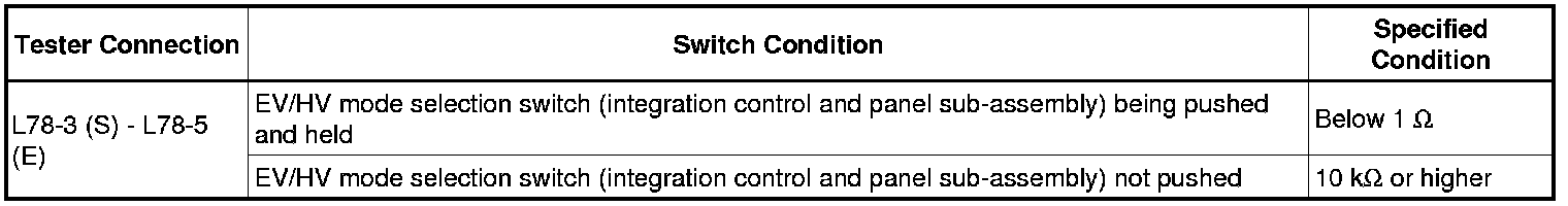
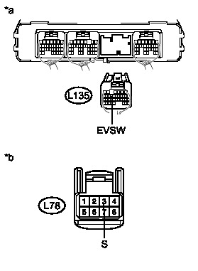
Text in Illustration

(c) Install the EV/HV mode selection switch (integration control and panel sub-assembly).
NG -- REPLACE EV/HV MODE SELECTION SWITCH (INTEGRATION CONTROL AND PANEL SUB-ASSEMBLY) Components
OK -- Continue to next step.
7. CHECK HARNESS AND CONNECTOR (EV/HV MODE SELECTION SWITCH (INTEGRATION CONTROL AND PANEL SUB-ASSEMBLY) - BODY GROUND)
(a) Disconnect connector L78 from the EV/HV mode selection switch (integration control and panel sub-assembly).
(b) Measure the resistance according to the value(s) in the table below.

Standard Resistance:
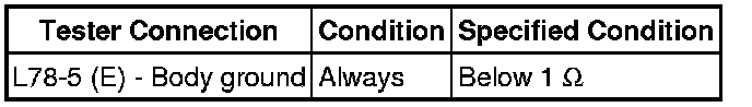
Text in Illustration

(c) Connect the EV/HV mode selection switch (integration control and panel sub-assembly) connector.
NG -- REPAIR OR REPLACE HARNESS OR CONNECTOR
OK -- Continue to next step.
8. CHECK HARNESS AND CONNECTOR (POWER MANAGEMENT CONTROL ECU - EV/HV MODE SELECTION SWITCH (INTEGRATION CONTROL AND PANEL)
(a) Disconnect connector L135 from the power management control ECU.
(b) Disconnect connector L78 from the EV/HV mode selection switch (integration control and panel sub-assembly).
(c) Measure the resistance according to the value(s) in the table below.
Standard Resistance:
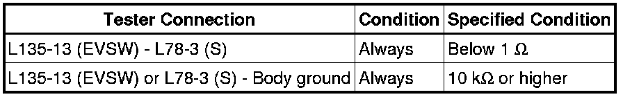
Text in Illustration
(d) Connect the EV/HV mode selection switch (integration control and panel sub-assembly) connector.
(e) Connect the power management control ECU connector.
NG -- REPAIR OR REPLACE HARNESS OR CONNECTOR
OK -- REPLACE POWER MANAGEMENT CONTROL ECU Removal