Charging Indicator Circuit
HYBRID / BATTERY CONTROL: PLUG-IN CHARGE CONTROL SYSTEM: Charging Indicator Circuit
- Charging Indicator Circuit
DESCRIPTION
The plug-in charge control ECU assembly illuminates the charging indicator to inform the driver that the vehicle is being plug-in charged. The plug-in charge control ECU assembly turns off the charging indicator when the plug-in charging completes successfully. The plug-in charge control ECU assembly also blinks the charging indicator if a plug-in charging malfunction occurs.
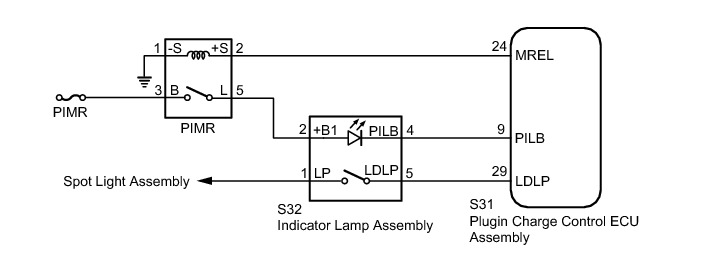
WIRING DIAGRAM
INSPECTION PROCEDURE
PROCEDURE
1. CHECK DTC OUTPUT (HEALTH CHECK)
(a) Connect the Techstream to the DLC3.
(b) Turn the power switch on (IG).
(c) Enter the following menus: Health Check.
(d) Check for DTCs.
Result:
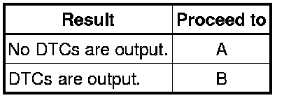
(e) Turn the power switch off.
B -- GO TO DTC CHART
A -- Continue to next step.
2. READ VALUE USING TECHSTREAM (CHARGE LID SW)
(a) Connect the Techstream to the DLC3.
(b) Turn the power switch on (IG).
(c) Enter the following menus: Powertrain / Plug-in Control / Data List / Charge Lid SW.
(d) Read the value displayed on the Techstream.
Result:
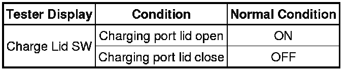
OK:
The Data List values change in accordance with the status of the charging port lid.
(e) Turn the power switch off.
NG -- GO TO LIGHTING SYSTEM How To Proceed With Troubleshooting
OK -- Continue to next step.
3. READ VALUE USING TECHSTREAM (CHARGE INDICATOR LIGHT STATUS)
(a) Connect the Techstream to the DLC3.
(b) Turn the power switch on (IG).
(c) Enter the following menus: Powertrain / Plug-in Control / Data List / Charge Indicator Light Status.
(d) Read the value displayed on the Techstream.
Result:
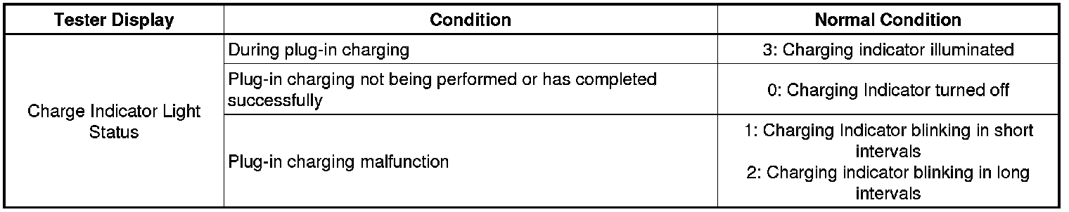
OK:
Operation of the charging indicator matches the display of the Data List.
(e) Turn the power switch off.
NG -- INSPECT INDICATOR LAMP ASSEMBLY (CHARGING INDICATOR)
OK -- GO TO PROBLEM SYMPTOMS TABLE Problem Symptoms Table
4. INSPECT INDICATOR LAMP ASSEMBLY (CHARGING INDICATOR)
(a) Remove the indicator lamp assembly.
(b) Check the charging indicator.
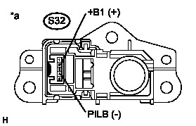
Result:
Text in Illustration
(c) Install the indicator lamp assembly.
NG -- REPLACE INDICATOR LAMP ASSEMBLY Components
OK -- Continue to next step.
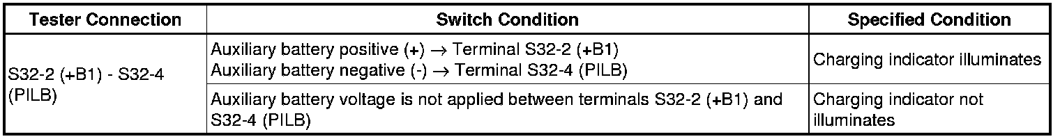
5. CHECK HARNESS AND CONNECTOR (PIMR RELAY - INDICATOR LAMP ASSEMBLY)
(a) Disconnect the connector S32 from the indicator lamp assembly.
(b) Turn the power switch on (IG).
(c) Measure the voltage according to the value(s) in the table below.

Standard Voltage:
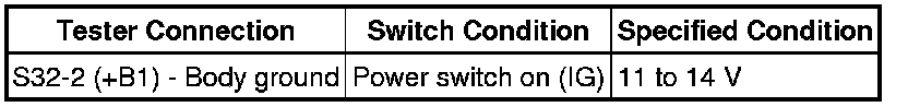
Text in Illustration
(d) Turn the power switch off.
(e) Connect the indicator lamp assembly connector.
NG -- REPAIR OR REPLACE HARNESS OR CONNECTOR
OK -- Continue to next step.
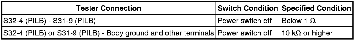
6. CHECK HARNESS AND CONNECTOR (INDICATOR LAMP ASSEMBLY - PLUG-IN CHARGE CONTROL ECU ASSEMBLY)
(a) Disconnect the connector S32 from the indicator lamp assembly.
(b) Disconnect connector S31 from the plug-in charge control ECU assembly.
(c) Measure the resistance according to the value(s) in the table below.
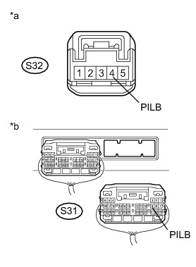
Standard Resistance:
Text in Illustration
(d) Connect the plug-in charge control ECU assembly connector.
(e) Connect the indicator lamp assembly connector.
NG -- REPAIR OR REPLACE HARNESS OR CONNECTOR
OK -- CHECK FOR INTERMITTENT PROBLEMS Check For Intermittent Problems