Check CAN Bus Lines for Short Circuit
NETWORKING: CAN COMMUNICATION SYSTEM: Check CAN Bus Lines for Short Circuit
- Check CAN Bus Lines for Short Circuit
DESCRIPTION
There may be a short circuit between the V bus main wires and/or CAN branch wires when the resistance between terminals 6 (CANH) and 14 (CANL) of the DLC3 is below 54 Ohms.
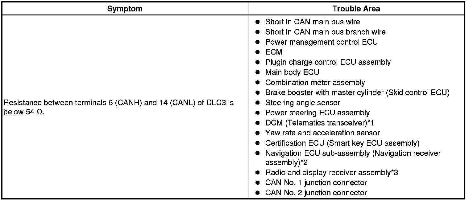
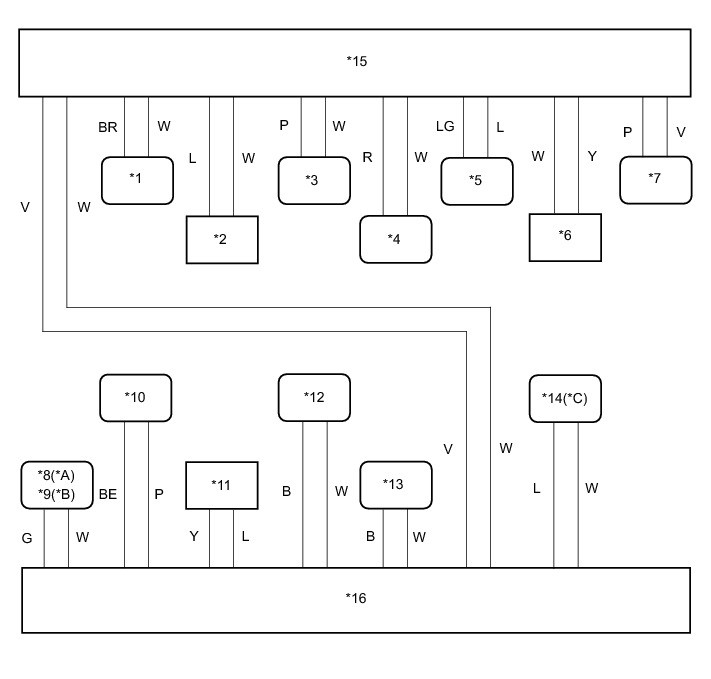
* *1: w/ Manual (SOS) switch
* *2: for Navigation receiver type
* *3: for Radio and display type
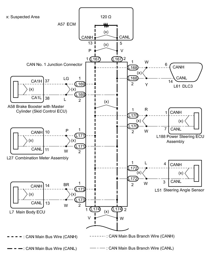
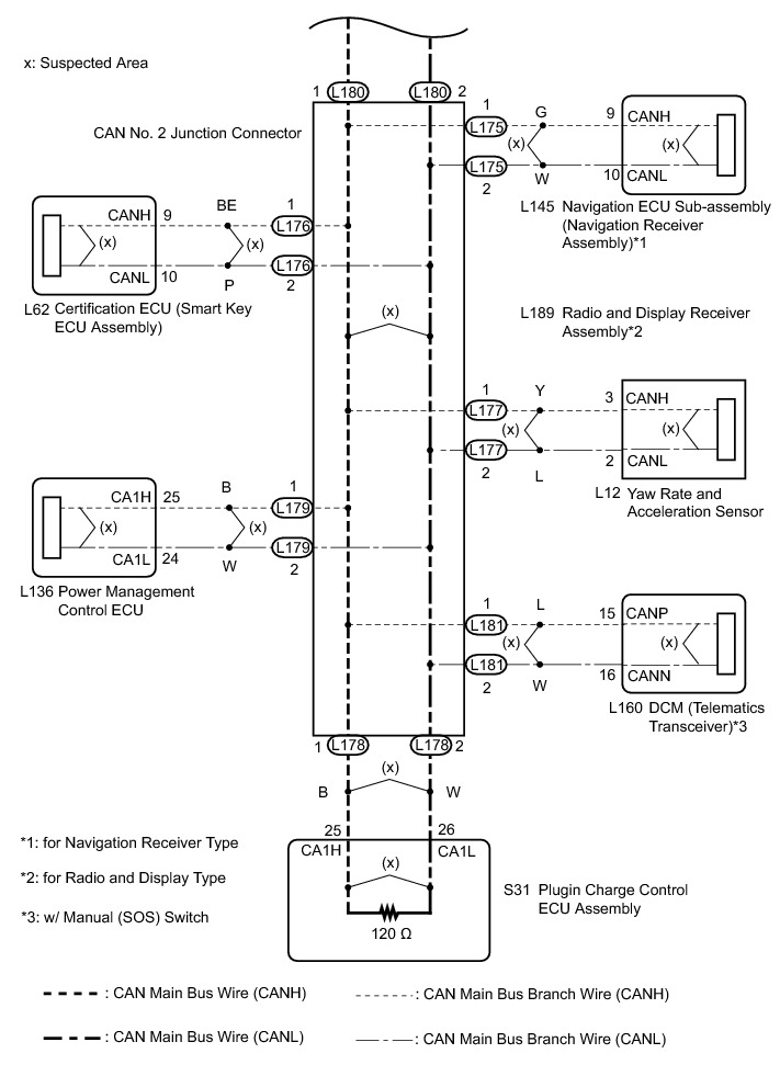
WIRING DIAGRAM
INSPECTION PROCEDURE
NOTICE:
* Turn the power switch off before measuring the resistances between CAN main bus wires and between CAN main bus branch wires.
* Turn the power switch off before inspecting CAN bus wires for a ground short.
* After the power switch is turned off, check that the key reminder warning system and light reminder warning system are not operating.
* Before measuring the resistance, leave the vehicle as is for at least 1 minute and do not operate the power switch, any other switches or the doors. If any doors need to be opened in order to check connectors, open the doors and leave them open.
HINT
* Operating the power switch, any other switches or a door triggers related ECU and sensor communication on the CAN. This communication will cause the resistance value to change.
* Even after DTCs are cleared, if a DTC is stored again after driving the vehicle for a while, the malfunction may be occurring due to vibration of the vehicle. In such a case, wiggling the ECUs or wire harness while performing the inspection below may help determine the cause of the malfunction.
PROCEDURE
1. CHECK FOR SHORT IN CAN BUS WIRES (DLC3 BRANCH WIRE)
(a) Disconnect the cable from the negative (-) auxiliary battery terminal.
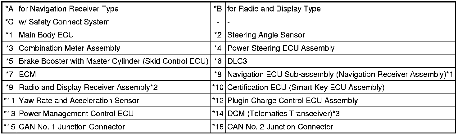
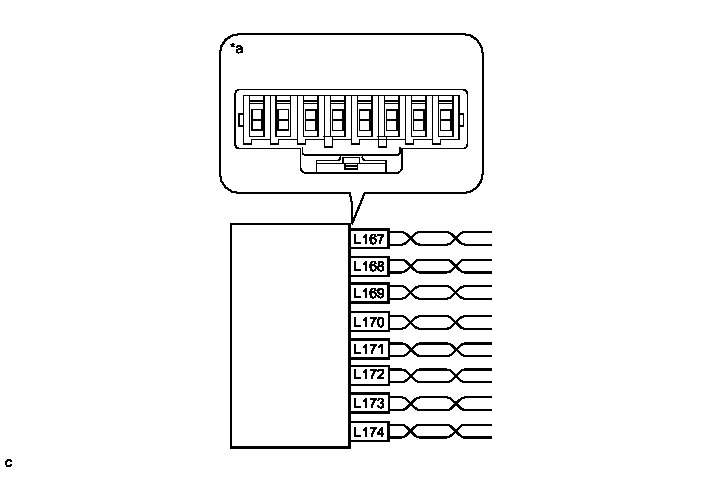
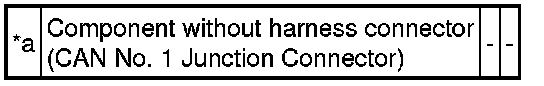
(b) Disconnect the DLC3 branch wire connector (L168) from the CAN No. 1 junction connector.
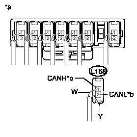
Text in Illustration
NOTICE:
* Before disconnecting the connector, make a note of where it is connected.
* Reconnect the connector to its original position.
(c) Measure the resistance according to the value(s) in the table below.

Standard Resistance:

Text in Illustration

NG -- REPAIR OR REPLACE CAN MAIN BUS BRANCH WIRE CONNECTED TO DLC3
OK -- Continue to next step.
2. CHECK FOR SHORT IN CAN BUS WIRES (BRANCH WIRE)
(a) Reconnect the DLC3 branch wire connector (L168) to the CAN No. 1 junction connector.
(b) Connect the probes of an ohmmeter to terminals 6 (CANH) and 14 (CANL) of the DLC3.
Text in Illustration

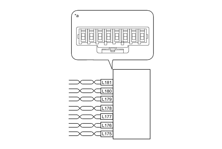
(c) While observing the resistance value shown on the tester, disconnect connectors (L169, L170, L171, L172, L173, L175, L176, L177, L179 and L181) from the CAN No. 1 junction connector or CAN No. 2 junction connector one by one until the resistance becomes normal (between 54 and 69 Ohms).
HINT
Disconnect the branch wire connectors other than those of the DLC3.
Text in Illustration
Text in Illustration
Wiring Color
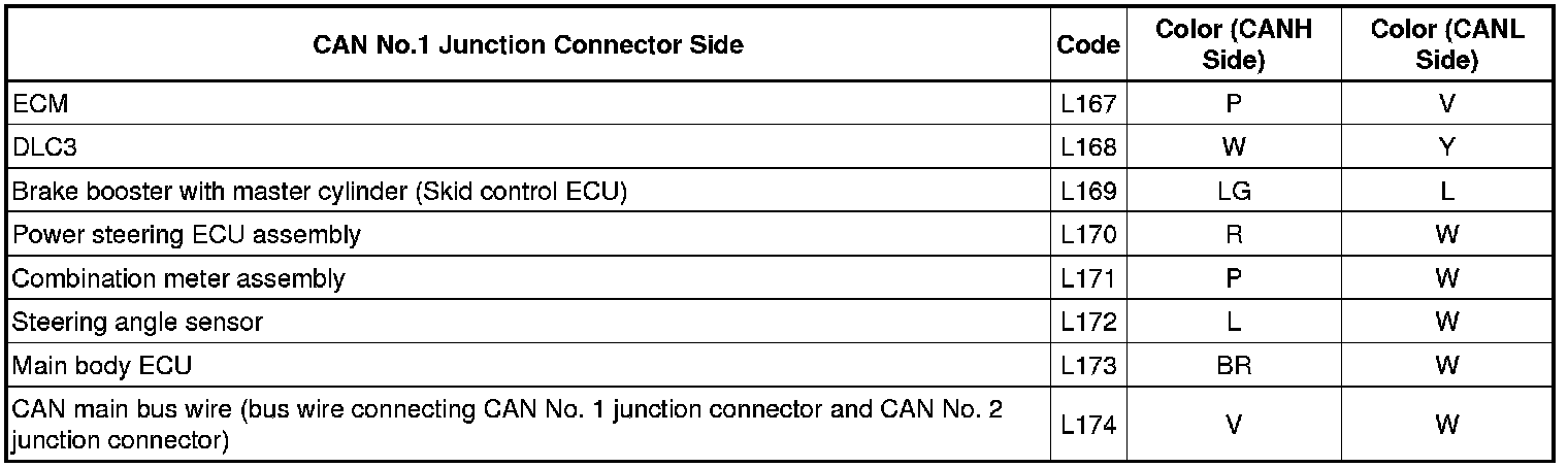
Text in Illustration
Wiring Color
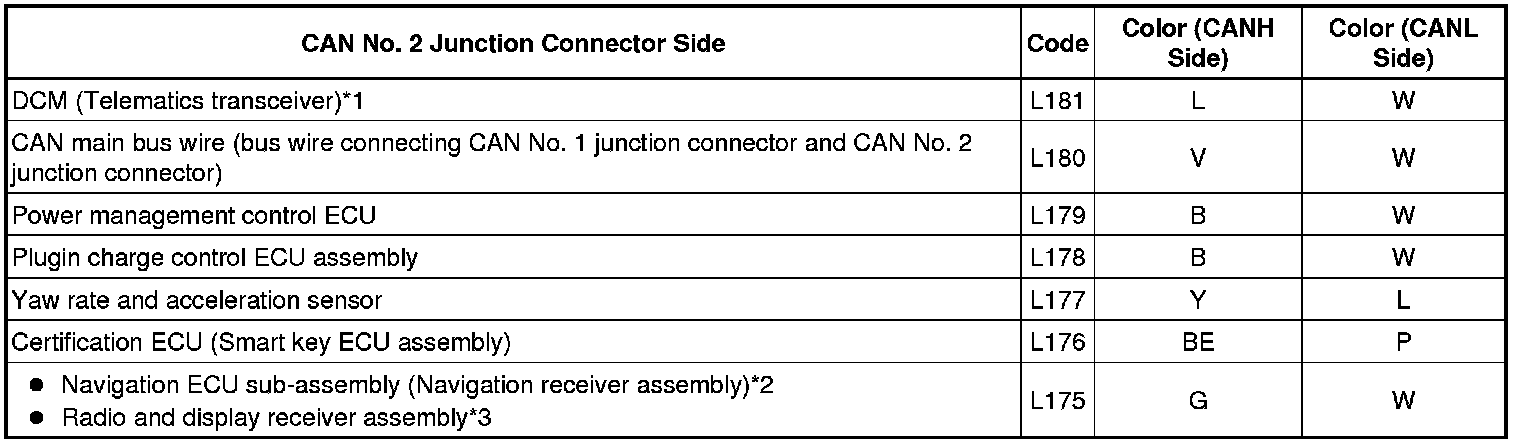
*1: w/ Manual (SOS) switch
*2: for Navigation receiver type
*3: for Radio and display type
NOTICE:
Do not reconnect the disconnected connectors until this inspection is complete because there may be a short in 2 or more branch wires.
Result:
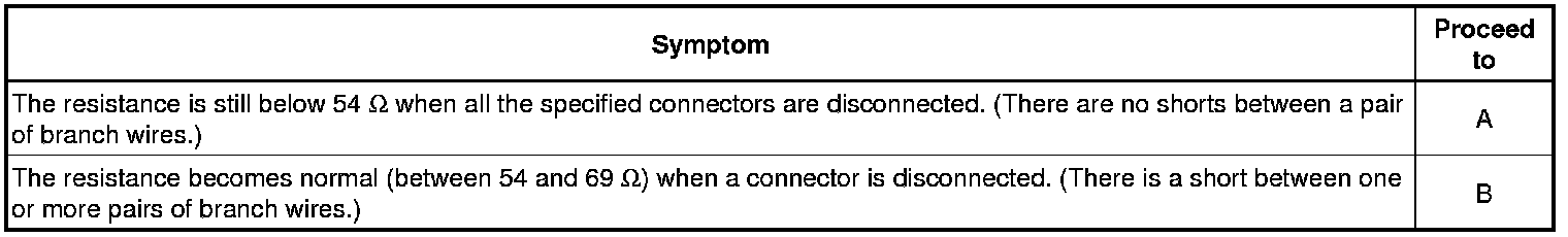
(d) When there is a short in one or more of the branch wires:
(1) Reconnect all of the connectors to the CAN J/C, except for the one that was disconnected last (the short-circuited bus wire). Check that the resistance shown on the tester is normal (between 54 and 69 Ohms) to confirm that there is a short in the one branch wire only.
HINT
* Connectors that connect to the CAN junction connector can be distinguished by the color of their CAN bus wires.
* Reconnecting the connectors to non-original positions on the CAN junction connector does not affect system performance. However, it is preferred to reconnect the connectors to their original positions to avoid negative effects on the wiring such as tension on the wiring harnesses, and to make future maintenance easier.
B -- CHECK FOR SHORT IN CAN BUS WIRES (ECU, SENSOR)
A -- Continue to next step.
3. CHECK FOR SHORT IN CAN BUS WIRES (PLUG-IN CHARGE CONTROL ECU ASSEMBLY MAIN BUS WIRE)
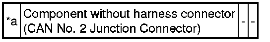
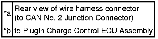
(a) Disconnect the plug-in charge control ECU assembly main bus wire connector (L178) from the CAN No. 2 junction connector.
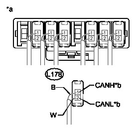
Text in Illustration
NOTICE:
* Before disconnecting the connector, make a note of where it is connected.
* Reconnect the connector to its original position.
(b) Measure the resistance according to the value(s) in the table below.
Standard Resistance:

Text in Illustration
Result:
B -- CHECK FOR SHORT IN CAN BUS WIRES (PLUG-IN CHARGE CONTROL ECU ASSEMBLY)
A -- Continue to next step.
4. CHECK FOR SHORT IN CAN BUS WIRES (ECM MAIN BUS WIRE)
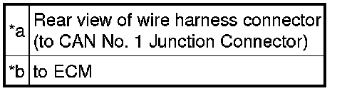
(a) Disconnect the ECM main bus wire connector (L167) from the CAN NO. 1 junction connector.
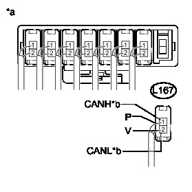
Text in Illustration
NOTICE:
* Before disconnecting the connector, make a note of where it is connected.
* Reconnect the connector to its original position.
(b) Measure the resistance according to the value(s) in the table below.
Standard Resistance:

Text in Illustration

HINT
Measure the resistance with the plug-in charge control ECU assembly main bus wire connector (BD) disconnected.
Result:
B -- CHECK FOR SHORT IN CAN BUS WIRES (ECM)
A -- Continue to next step.
5. CHECK FOR SHORT IN CAN BUS WIRES (CAN NO. 1 J/C)
(a) Disconnect the CAN main bus wire connector (L174) from the CAN No. 1 junction connector.
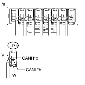
Text in Illustration
NOTICE:
* Before disconnecting the connector, make a note of where it is connected.
* Reconnect the connector to its original position.
(b) Measure the resistance according to the value(s) in the table below.
Standard Resistance:

Text in Illustration

NG -- REPLACE CAN NO. 1 JUNCTION CONNECTOR
OK -- Continue to next step.
6. CHECK FOR SHORT IN CAN BUS WIRES (CAN NO. 1 J/C - CAN NO. 2 J/C)
(a) Reconnect the CAN main bus wire connector (L174) to the CAN No. 1 junction connector.
(b) Disconnect the CAN main bus wire connector (L180) from the CAN No. 2 junction connector.
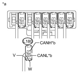
Text in Illustration
NOTICE:
* Before disconnecting the connector, make a note of where it is connected.
* Reconnect the connector to its original position.
(c) Measure the resistance according to the value(s) in the table below.
Standard Resistance:

Text in Illustration

NG -- REPAIR OR REPLACE CAN MAIN BUS WIRES (CAN NO. 1 J/C - CAN NO. 2 J/C)
OK -- REPLACE CAN NO. 2 JUNCTION CONNECTOR
7. CHECK FOR SHORT IN CAN BUS WIRES (ECU, SENSOR)
(a) Reconnect the connector for the short-circuited branch wire to the CAN J/C (the connector that caused the bus wire resistance to become normal (between 54 and 69 Ohms) when it was disconnected).
(b) Disconnect the connector that includes the DLC3 connected CAN wires (such as CANH and CANL) from the ECU (or sensor) to which the short-circuited branch wire is connected CAN Communication System.
(c) Measure the resistance according to the value(s) in the table below.
Standard Resistance:

Text in Illustration

HINT
If the resistance becomes normal (between 54 and 69 Ohms) when the connector is disconnected from the ECU (or sensor), there may be a short in the ECU (or sensor).
NG -- REPAIR OR REPLACE CORRESPONDING ECU OR SENSOR BRANCH WIRES OR CONNECTOR
OK -- REPLACE CORRESPONDING ECU OR SENSOR
8. CHECK FOR SHORT IN CAN BUS WIRES (PLUG-IN CHARGE CONTROL ECU ASSEMBLY)
(a) Reconnect the plug-in charge control ECU assembly main bus wire connector (L178) to the CAN No. 2 junction connector.
(b) Disconnect the plug-in charge control ECU assembly connector.
(c) Measure the resistance according to the value(s) in the table below.
Standard Resistance:

Text in Illustration

HINT
If the resistance becomes normal (between 108 to 132 Ohms) when the connector is disconnected, there may be a short in the plug-in charge control ECU assembly.
NG -- REPAIR OR REPLACE CAN MAIN BUS WIRES (PLUG-IN CHARGE CONTROL ECU ASSEMBLY MAIN WIRES)
OK -- REPLACE PLUG-IN CHARGE CONTROL ECU ASSEMBLY Removal
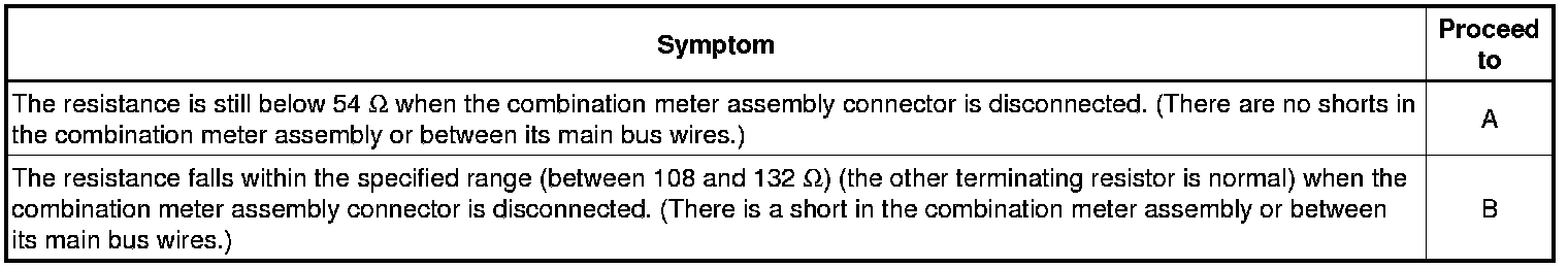
9. CHECK FOR SHORT IN CAN BUS WIRES (ECM)
(a) Reconnect the ECM main bus line connector (L167) to the CAN No. 1 junction connector.
(b) Disconnect the ECM connector.
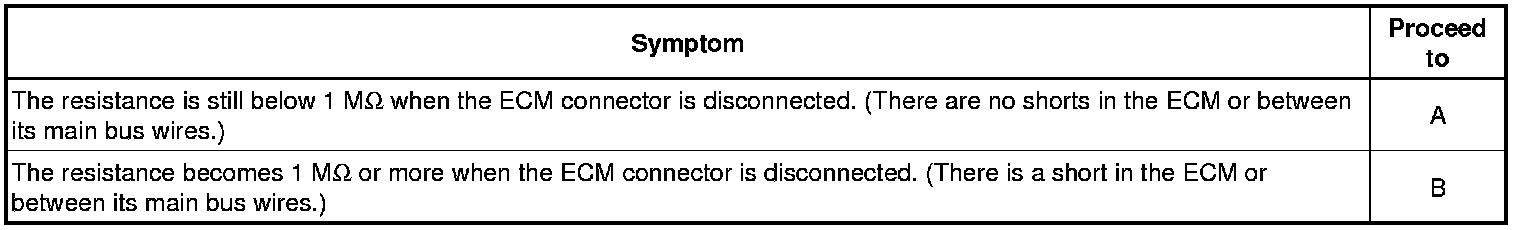
(c) Measure the resistance according to the value(s) in the table below.
Standard Resistance:

Text in Illustration

HINT
* Measure the resistance with the plug-in charge control ECU assembly main bus wire connector (BD) disconnected.
* If the resistance changes to 1 MOhms or more when the connector is disconnected, there may be a short in the ECM.
NG -- REPAIR OR REPLACE CAN MAIN BUS WIRES (ECM MAIN WIRES)
OK -- REPLACE ECM Removal